 |
|
|
|
|
|
|
|
|
|
|
|
|
|
|
|
|
|
|
|
|
|
|
|
|
|
|
|
|
|
|
|
|
|
|
|
|
|
 |
|
|
|
Radio Restoration |
|
|
|
|
 |
|
|
|
Electronic Restoration of the Emerson DB-301 |
|
|
|
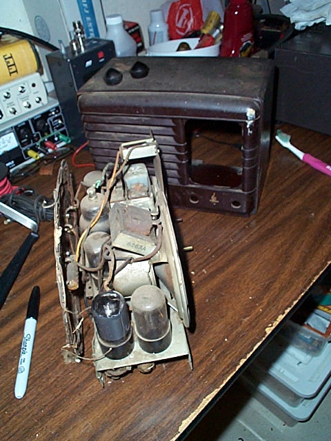
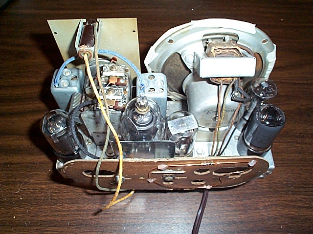
The photo below (left) shows the chassis after it was pulled from the cabinet. I removed and cleaned the tubes. The tube on the lower left of this photo was cleaned and put back in just to provide a sense of how dirty the radio was. The chassis was cleaned using Windex and, on the more stubborn areas, mineral spirits. The result is shown on the right. |
|
|
|
 |
|
|
|
 |
|
|
|
|
|
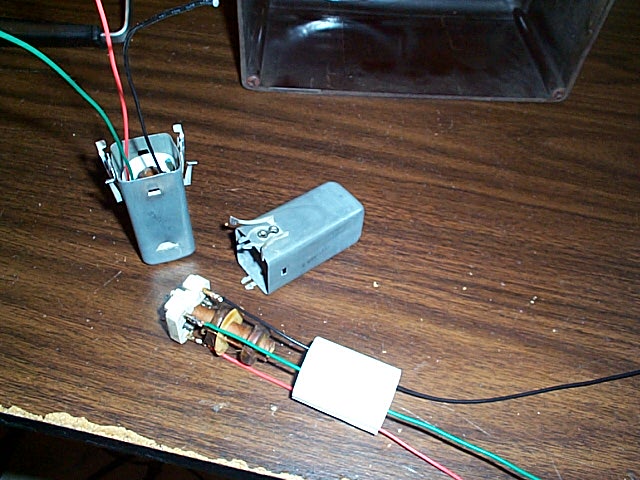
Some of the wiring needed to be replaced. In particular, I did this to the intermediate-frequency (IF) transformers because the insulation on their original wires was cracked. The partially rebuild "IF cans" are shown below. |
|
|
|
 |
|
|
|
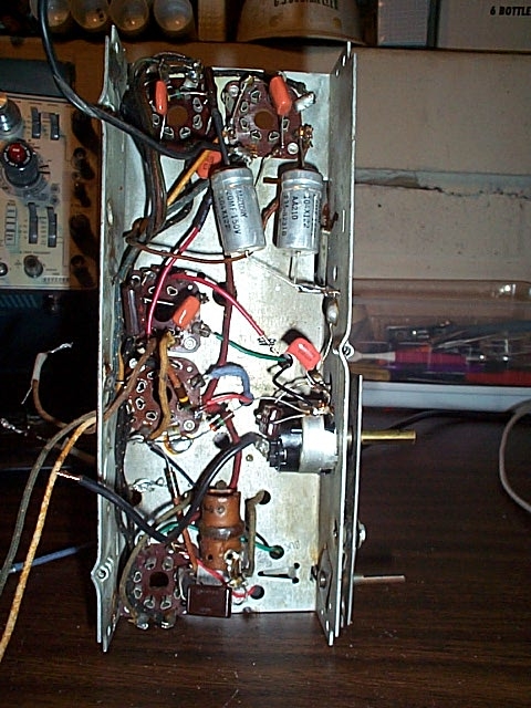
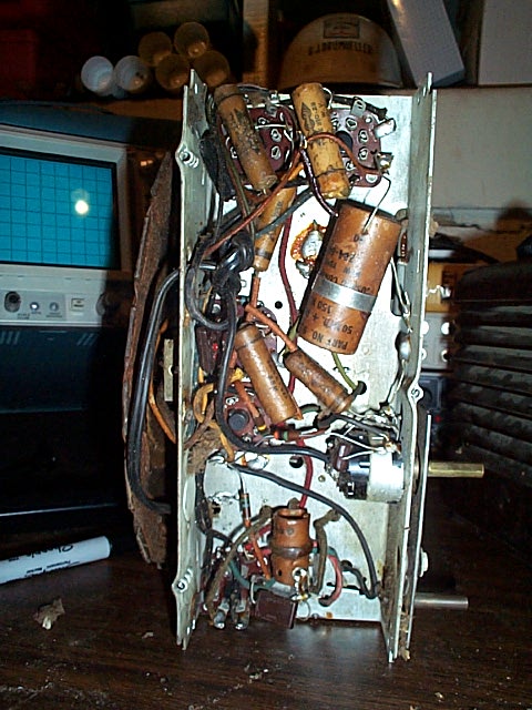
For stafety and reliability, I replaced all of the paper and electolytic capacitors. These components are notorious for not working in radios this old. Below are views of the chassis before (left) and and during (right) "re-capping." |
|
|
|
 |
|
|
 |
|
|
|
|
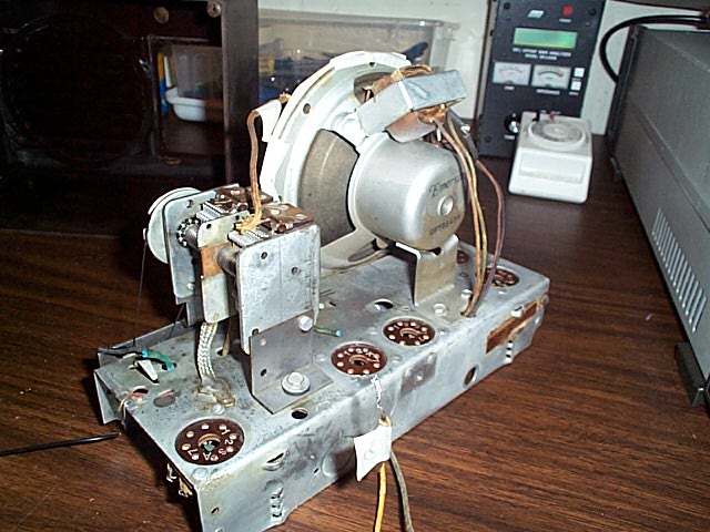
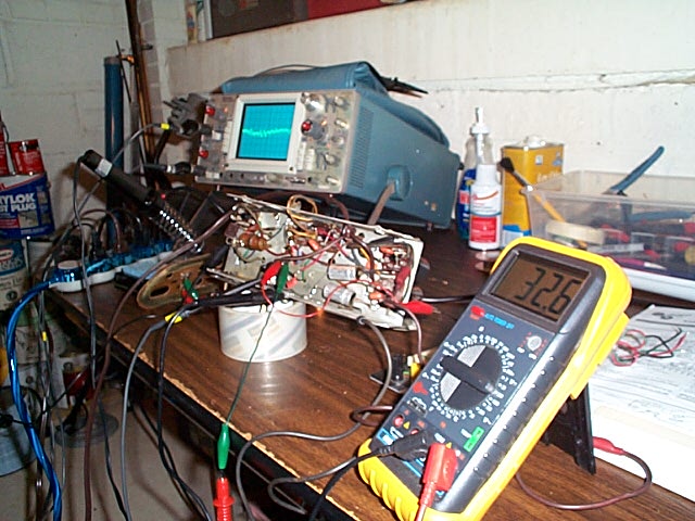
After replacing the capacitors, I put the tubes back in and turned it on. It worked! The picture below shows the chassis being bench tested. The audio signal is on the scope. Because the transformers were rewired, I had to do a complete realignment of the IF stages |
|
|
|
 |
|
|
|
Because the original "spider web" antenna was damaged and I was not inclined to rebuild it, I installed a replacement. This required the following modifications visible in the photo below: The original trimmers on the ganged tuning capacitors did not offer sufficient adjustment for accurate dial tracking, so I bridged them with new ones. Due to coupling between the second IF amplifier tube and the new antenna, the radio oscillated on the low end of the dial. This was cured by fabricating and installing a metal shield between the antenna and tube. Finally, the tuner was aligned, and this required a slight reduction in antenna inductance. This was accomplished by placing a small loop of wire on the back of the antenna. |
|
|
|
 |
|
|
|
 |
|
|
|
Click on the icon to see where I'm doing all this work. |
|
|
|