All the write ups on Dpfi to Mpfi all left alot of things unclear so here is a write up with pictures that is more clear. This writeup is for Dpfi to Mpfi on a B16a1. Its the same for if your switching the intake manifold but you will need some additional parts. These being then intake manifold and throttle body with ball sensors, fuel rail, injectors, and an 88-91 Si ecu and distributor.
Things Needed
Si wiring harness
Dpfi wiring harness
Si resistor box
Plugs that go on knock sensor, Vtec solenoid, and oil pressure sensor. Or a subharness you can get on ebay or from < a href="http://www.geocities.com/jopivym/www.hasport.com">Hasport.
16 gauge wire (about 30-40 feet)
lots of electrical tape
8 wire connectors that snap together
wire loom
There are a few things you have to do to convert your car to Mpfi. These are fuel injectors, crank angle sensor, distributor plug, and lengthen the EACV and TPS. But on the TPS you must switch 2 wires. We'll get into that later. On all your wire connections I'm not just recomending that you solder the connections, I'm saying it's mandatory.
In the Car
Pins B10 and B12 are empty. For pins for these goto B2 and B11. Now cut C1 and C2 off. Connect orange wire to B10 and white wire to B12. Run C1 and C2 into the engine compartment. Put a wire connectors on them and mark them for later. Now cut wires A3 and A7. Run the ecu side into engine compartment. Put connectors on them and mark them. Now Run wires A8, C8 if your runing 2 O2 sensors, C16 if your runing 1, B5 and B19 into engine compartment. Put connectors on them and mark them.
Under the Hood
TPS & EACV
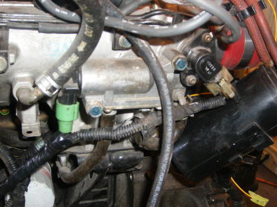
I started off by geting my Dpfi wiring harness wraped around the motor how its going to sit. I put it on all the plugs I could. Then I lengthened the TPS and EACV. The TPS is on the throttle body on the opposite side of the trottle cable. The EACV is on the back of the intake manifold and it plugs Strait up. Before you lengthen these bolt the wiring harness onto the valve cover so you can get just the right length for a clean install. The EACV is a green plug and the TPS is white. On the TPS the switch the green/white wire with the yellow/white wire. This is because on the Dpfi it is opposite. In picture TPS is on the right and EACV is on the left.
Distributor & Crank Angle Sensor
Next is the distributor and crank angle sensor. On bthe Si and B16a1 motor the distributor has 7 wires and the Dx or Std have 5. This is because the Mpfi motors have a crank angle sensor. What you'll need to do for this is cut the Dx distributor plug off the Dx distributor. Be careful, there are 2 white wires and right by the plug there is a small piece of red tape on one of the white wires. This is the only way to tell them apart. Now cut the plug off of the distributor on the motor, while paying attention to which white wire has the red tape, and match the colors of the wires off the distributo to the wires on the Dx distributor plug. If you get the white wires confused just don't solder them and wait til you fire the motor up to see if they are right. Now plug the distributor plugs together. There will be 2 wires left coming out of the distributo, a blue/green and a blue/yellow. These are for the crank angle sensor. Blue/green go's to C1 and blue/yellow go's to C2. I ran these wires right to the back of the tranny, put wire connectors on them, and put a piece of tape on the ends, with their destination, so I knew where they go.
Injectors
Now its time for the injectors. Just cut the Si wiring harness on tranny side of the wiring harness. Undo the wire loom and keep the red/black wires that go from the injector plugs to the injector resistor. Cut the other wire that comes out of each injector3 or 4 inches from the injector plug. Cut the yellow/black wire that go's from the resistor to then main engine harness plug off by the harness plug. Run this to the yellow/black wire to the yellow/black wire on the primary injector on the Dx harness. The primary injector is a green plug with a yellow and yellow/black wire coming out of it. If you do it that way it eliminates runing the injector plugs to the resistor. Just trying to make it easier. Now on the first injector there is a brown wire coming out. Connect it to the yellow wire on the primary injector. On the third injector there is a light blue wire, connect it to the red wire on the secondary injector on the Dx harness. The secondary injector is a brown plug that has a red and a yelow/black wire coming out of it. The second injector has a red wire, this go's to A3. The fourth injector has a yellow wire, run this to A7. I ran these 2 wires down to where I ran the crank angle sensor wires, put wire connectors on them and put a piece of tape that said where they where going. In picture are the Dpfi injector plugs.
B16a1 Sub-harness
You need to add a knock sensor, Vtec solenoid, oil pressure sensor, and 2nd O2 sensor. Get the plugs for these and plug them all in. The knock sensor go's to B19, Vtec solenoid to A8, oil pressure sensor to b5, and 2nd O2 sensor to c8. If you only want to run 1 O2 sensor, wire 2nd O2 into 1st and wire this to C16. I ran these down to where I have been ran the crank angle sensor wires, put wire connectors on them, and wrote where the wires where going on tape on them.
Finish it all up
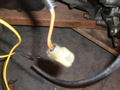
Now all that's left is to connect the wire connectors and wrap everything in wire loom. I used my mom's nail polish and painted all the connectors different colors for if I take the motor out. The picture is of the leftover plug. It is on the back by the EACV and TPS.