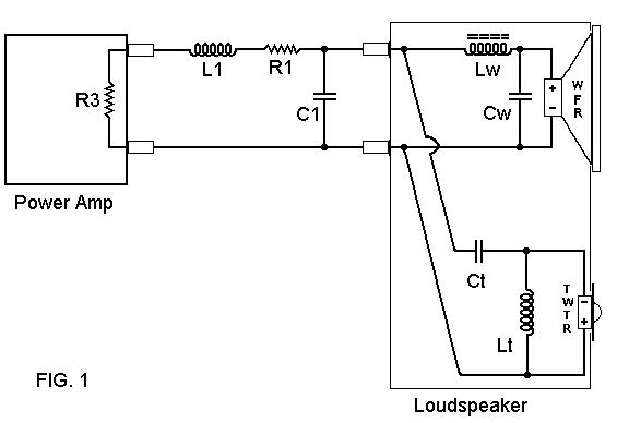
Fig. 1 shows a typical single wired speaker system, with a second order (12 dB/oct) crossover included. The speaker crossover components Lw, Cw, Lt and Ct are inside the speaker.
The lumped sum cable electrical parameters are shown as L1, R1, and C1.
The amplifier output impedance is shown as Ra.
Fig. 2 shows a bi-wiring connection, with the additional circuit elements it has.
Fig. 3 shows the woofer and tweeter as AC generator signal sources.
Fig. 4 shows the simplified circuit diagram for analyzing the bi-wire vs. the single wire.
Fig. 5 shows the attenuation of inter-driver IM due to bi-wiring when the second bi-wire cable is adding a second cable same as the first (a common way folks bi-wire).
Fig. 6 shows the attenuation of inter-driver IM due to bi-wiring when
the single wiring has an equal resistance.
This is the way the cable naysayers insist that it be compared.
Simplifications and assumptions:
Cable capacitance is going to be negligible from a signal attenuation
standpoint. This does not mean that it has no audible effect, just
that it does not figure into these simple first approximation calculations.
Cable inductance is going to be negligible from a signal attenuation standpoint in the typical crossover range of a two-way speaker system. For some really high inductance cables, this will not be a good assumption, as they are significantly inductive down to 3 kHz.
Connection resistance is considered to be negligible.
So we are going to look at the simple resistive attenuation that bi-wiring provides vs. a single wiring circuit, given that the two speakers can both act as generators and attempt to send spurious signals to one another. Generator source resistance is taken to be 8 ohms, as is the effective load resistance of the other driver. Cable length is a reasonable 15 foot length for both a single wired speaker cable, and for each of the bi-wire cables.
First analysis based on the common practice of adding a second cable the same as the first one. This has the total bi-wiring resistance half that of the single wiring,
Second analysis based on maintaining equal resistance between the single wire case, and the bi-wiring case.
The table does not include the effects of the crossover components,
that is, it is shown as a broadband resistive attenuation.
In practice, the loudspeaker system crossover will tend to limit the
attenuation effects to around the electrical crossover frequency, for about
an octave or so on either side.
Some might think that the presence of the crossover components will totally throw this resistively based analysis off. While it will change the numbers a bit, the fact that I used the nominal loudspeaker load resistance of 8 ohms, means that for real world speakers that tend to actually run lower than that, the amount of extra impedance added by crossover components that are at approx. a similar impedance as the drivers, which when added to the real world impedance of the drivers at 6-7 ohms, totals about 10-12 ohms, not too far off from the 8 ohms nominal. So for the region of interest centered around the crossover, these numbers will do for a first approximation.
This does mean that the effects of such "cross-driver signal attenuation" will be limited to a region of about 2 octaves centered on the electrical crossover frequency point.
The crossover roll off itself may be considered as part of the reduction,
but this roll off is applied to both the signal coming from the tweeter
bi-wire speaker cable AND to the single speaker cable, so that any advantage
this represents will be present for both cables
equally.
Single WIring Circuit Diagram

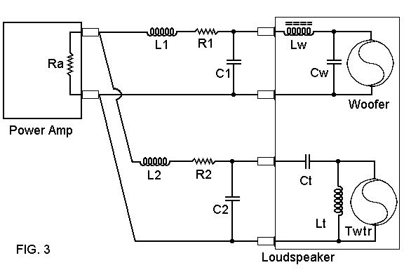
Woofer and Tweeter shown as signal generator sources
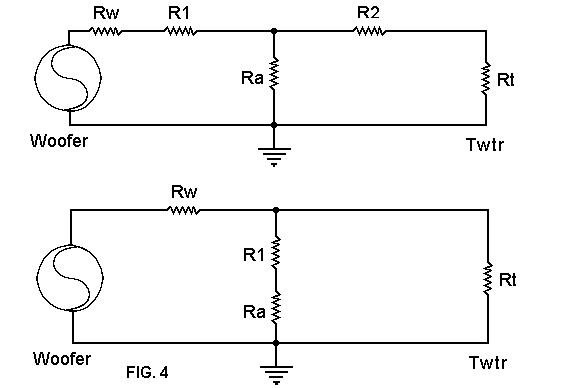
SImplified Circuit for Analysis, Bi-Wiring Circuit
on top, Single Wiring Circuit on the bottom
Only the woofer into the tweeter portion is shown, the tweeter can also attempt to send a signal into the woofer.

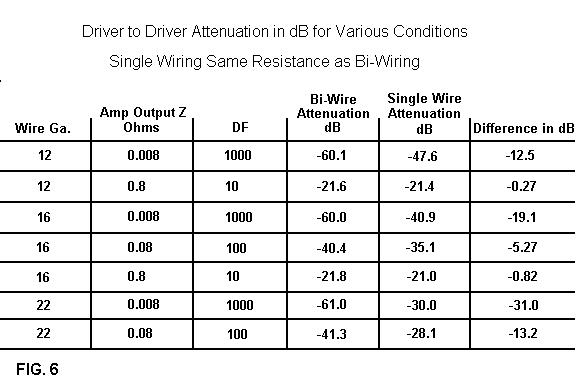
2nd Set of Conditions - Single wiring resistance same
as Bi-wiring total resistance.
If we examine the results of this simplified first approximation analysis, we see that use of small wires for speaker cable, as sometimes practiced to keep skin effect issues to a minimum, tends to increase the attenuation of the inter-driver IM.
Very low output Z power amplifiers also tend to increase the attenuation of the inter-driver IM.
However, high output Z power amps used with large speaker cable wires having low resistance shows very little improvement over single wiring. This does not mean that all such power amps, which include most tube amps, and certain low negative feedback SS amps, will not respond at all to bi-wiring, as this is only one aspect of several with regard to bi-wiring differing from single wiring.
What are the sources of the speaker drivers feeding signal back into
the crossovers? Well, there are two sources.
One source would any resonant behavior in a given driver, whatever
the reason for the resonance. Woofers have a fundamental resonance
that is a single peak in a closed (sealed) box, or a double peak in a vented
enclosure, but they also have some cone and suspension related resonances
at higher frequencies too. These often show up as small wrinkles
in the impedance curve, that correlate to small bumps or a bump/dip in
the speakers response, and these can be seen in the amplitude response
by using a time domain waterfall response function.
Tweeters have a fundamental resonance well within the audio band, often
just one octave or less below the crossover frequency. This is a
prime candidate for a spurious signal as well.
The other source is the output from the OTHER speaker, that is, the
woofer feeding into the tweeter, and vice versa.
That data is on page 3, use the link below.
All applicable copyright laws apply, all rights reserved, except transmission by USENET and like facilities granted. Any use or inclusion in print or other media are specifically prohibited. The informational content is not warrantied in any way or form, and any use of said content are at the reader's own risk, the author shall not be held responsible in any way for any damages or injuries arising from the content of this web site. Common safety practices are encouraged at all times. Do not fold, spindle or mutilate.