 |
|
|
|
|
|
|
|
|
|
|
|
|
|
|
|
|
|
|
|
|
|
|
|
|
|
|
|
|
|
Page Six
|
|
|
|
 |
|
 |
|
|
|
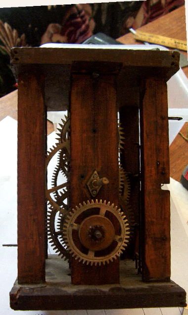
Left dial trail of the clock view 1 Bottom gear and pinion 24/10
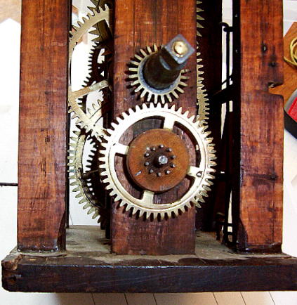
RIGHT Dial train hour cannon gear added 24 teeth |
|
|
|
|
|
|
|
|
|
This clock is powered by a chain and weight. The shaft for this gear comes thru the front center pillar and has the center bottom gear press fit to it. When the hands are turned to set the time this gear rotates on the shaft |
|
|
|
|

|
|
|
|
|
|
|
 |
|
|
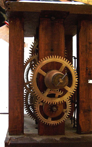
RIGHT the dial train complete with the second cannon gear slipped over the first.
the hour cannon gear has 60 teeth. The 12/1 ratio is accomplished by a 48/24 and a 60/10 meshing |
|
|
|
|
|
|
 |
|
|
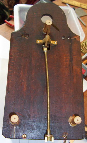
The back of the clock held away from the wall by 3 pegs. The top one serves double duty as the axis for the pendulum swing
Note The large hole in the top of the back plate. These clocks were designed to be sold without a case and simply wag on the wall.
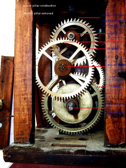
the clock is completely hand made.The plates and pillars and the hubs of the gear wheels are spruce. The wheels are brass and are case before the teeth are cut. In many places there is evidence of some sort of lathe circles graved below the wheels are not complete (wheels not exactly at right angles to the axis of rotation . Throughout the clock is the use of gears with numbers of teeth at multiples of 7 |
|
|
|
|
|
 |
|
|
|
|
|
The anlges on the teeth of the escape wheel are 7 leading face and 28 trailing face. Now this to the lay person is just so many numbers but to the horologist there is the intreging question of why use multiples of 7. This is certainly difficult to lay out by hand. I suspect that it was a matter of using a compass set around the circumfrnace till the right distance was found and then using the resulting gear to index the rest. DO YOU HAVE ANY IDEAS? Why not email me as I would be very interested. |
|
|
|
|
|
 |
|
|
|
|
To Home Page |
|
|
|
|