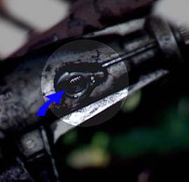
| On
the C3: Your first task is to remove the brass threaded
unions at the front of the box which connect the transmission
oil cooler pipes. On the A4LD: These have been
enlarged, therefore, simply replace these with the unions
you've just removed from your old C3 unit. |
|
|
|
|
|
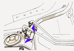
It
is essential that these pipes are in good condition. Any
seepage can result in poor performance and can lead to
over-heating and eventual failure. If in any doubt, replace
them.
ED:
Ford no-longer
produce these pipes, although, there are a number of
companies who can reproduce them, however, they are
very expensive.
One
solution (and
a route I have taken)
is to have the pipes reproduced in high pressure plastic.
This was done by a local hydraulics firm. The new pipes
have the advantage of being flexible and corrosion free.
I used this method for almost 8 years without any problems
|
|
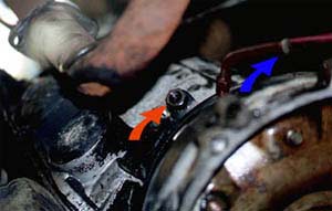
The
final consideration is the Speedo drive. The A4LD as
fitted to the MK3 utilizes an electronic Speedo, however,
Ford retained the original location and type of fixing
as found in the C3, therefore its simply a matter of
removing the electronic drive from the A4lLD and replacing
it with the mechanical Speedo drive from the C3
|
|
|
|
|
|
At
this point there is nothing more to do to the transmission,
so its time to move under the car.
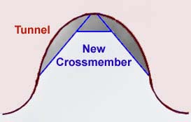
About
half way along the transmission tunnel there is a shaped
crossmember that follows the curve of the tunnel. This
must be removed. Due to the extra length of the A4LD
unit, the rubber coupling on the propshaft is now aligned
with this crossmember and it will foul.
After
removal, a replacement crossmember will be required
further down the tunnel. As it would be difficult to
reproduce the curve an alternative is required.
(See
diagram left)
|
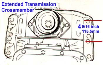
| Next,
the transmission crossmember.
The
mounting point for the A4LD sits further back
than the old transmission therefore your old crossmember
is no-longer suitable. However, there is a solution.
2
brackets need to be manufactured then mounted to the
original C3 crossmember moving it reward approximately
4 9/16 inch (15.5mm).
ED:
One other solution to this problem would be to remove
the adjustable mounts from a MK3 and weld them on to
the MK2 . With this method accuracy is not so essential.
Once
completed the next stage (if not already done is to
remove the 3 sp shifter from the car.
|
|
ED:
Since completing this project, I now suspect that the
curved (boomerang) shaped crossmember from a Manual
Cortina maybe the right size; as yet I have tried this
but I will soon.
|
|
|
|
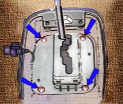
Depending
on which shifter is used, some material may need to be
removed from around the transmission tunnel to allow the
shifter to drop into position. Aprox 1 1/2 inch (32mm)
from the front and aprox 3/4 inch (19mm) from the rear.
A good primer and/or underseal should be applied around
the edge of the cut to protect against corrosion
Attach with 4 self taping bolt head screws to ensure
a good fixing
Later
shifters require less material to be removed and if
you can find an Ultima unit, these look like they
might be a straight swap.
|
| All
A4LD Torque Converts contain a locking mechanism. The
locking mechanism is designed to engage at various predetermined
speeds of the converter resulting in improved driveline
efficiency and fuel economy.
On
the early models this was a centrifugally operated locking
clutch mechanism, negating the use of electrical or
hydraulic lock-up components.
However,
these are now quite rare, later units became electronically
controlled by the ECU. This improved drivability further.
ED:
Latest Update. Since
completing this project I have tried several methods
to engage the locking mechanism, however, all have proven
to be unreliable, however, I'm now working on installing
the complete EFi system and ECU so hope to have a locking
system working shortly!
|
|
|
| Once
this work has been completed its time to fit the transmission
following the standard installation procedures.
|
|
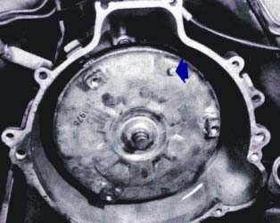
ED:
It should be noted that you can use the Torque Converter
from your C3 transmission (Above)
rather that the locking
unit. This has the added advantage of having a drain plug,
should the need
to drain the system
arise. |
|
|
|
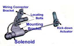
On
post 1986 models the kick-down facility was redesigned.
Rather than the usual cable controlled unit, later models
were fitted with solenoid controlled system.
|
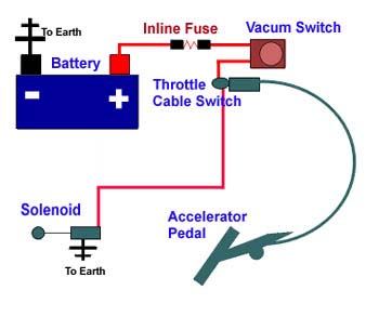
| This
is not a problem when retro-fitting the A4LD into the
MK2. Simply fit the MK3 throttle cable (with built in
switch) and wire via a (20
amp) fused link
and vacuum switch to the battery.
(See Diagram).
The
vacuum switch can be mounted anywhere inside the engine
bay, however, it requires a connection to the vehicle
vacuum system,
(I have mounted it next to the ignition coil),
It should be mounted somewhere between the Throttle
Cable Switch and a vacuum source.
The
MK3 cable differs from the MK2 at the pedal, however,
its quite simple to remove the MK2 pedal and drill out
a dome shape to accept the MK3 cable, although, at this
point, I intend to try a MK3 pedal, this may make it
easier to fit the cable
|
|
|
| Next
the selector linkage. I used the MK3 linkage which came
with the selector. There is enough adjustment available
in this component, therefore no modifications are required. |
| Finaly,
depending on which sellector you have used, a trim surround
for the gear selector and consol is required. If you have
used the older type 'Manual Style' selector then you can
use two surrounds from the MK3, Simply glue the second
to the first and slip over the selector. |