Off-Road Light�s Mounting and Wiring
This write up will describe how I mounted and wired up my off-road lights. There�s other ways, and I�m sure ways that look better than how I did it. If you don�t like how I did mine, then the only part of this write up that might be of use to you will be the wiring section.
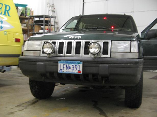
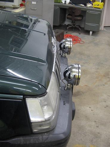
With the grand Cherokee, there aren�t many choices of where to mount unless you have a bull bar on the front. I didn�t want to lose anymore height clearance by mounting on the roof, so I went with the front bumper. Another reason I mounted there is because the way I did it makes it almost impossible to steal without taking a good deal of time to work on it.
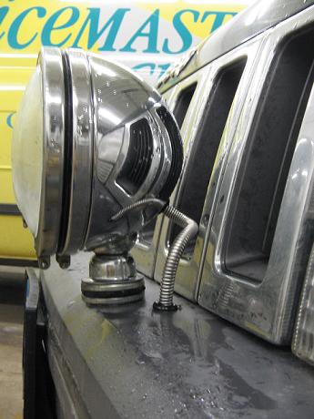
For lights, I was on a rather tight budget, and I wanted something that would light up the road rather well when I�m traveling late at night. I was directed towards an eBay auction that was selling 6 �� Eagle Eye 150w off road lights. After shipping costs, the final price I paid was 60 dollars. The person I bought mine from still runs several auctions selling the same thing. They came with Wagner bulbs, so they�re not some cheap garbage.
I first found a good place that would provide enough support to keep the lights steady when going down the road, hitting bumps, and bouncing around when off-roading. I took off the bumper cover entirely, and found two bolts that go through the black mounting piece that all the lighting assemblies mount to and into the actual bumper. They were far enough in front of the grill that if I used those as support spots, the new lights wouldn�t be in front of the headlights.
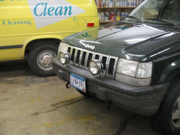
After I found the two bolts, I decided on how to use them. I ended up getting a 4 foot 1/8� thick piece of metal, about 2 inches wide. I then cut out four pieces, each being about 4 inches long. I drilled matching holes on each of them one end to be where the previously found bolts will go through. I decided how far out from the bolt I wanted the lights to sit, and then I carefully drilled matching holes on all of them on the opposite ends, all exactly the same length as each other. I made the holes just out far enough so they�d sit about half an inch in front of the grille.
I used two of the little plates with holes for each light, just to make sure there was more than enough support. I placed two of each of the plates under each bolt, and tightened it down to make sure they�d hold still. I left the factory black piece underneath so it wouldn�t be lifting up from having �� of metal plate underneath it. I also didn�t tighten it so much that it might possibly crack or break the black plastic.
After I had them mounted in place where I wanted them to be, I took out the foam insert from the bumper cover. I took the bumper cover and put it back on the Jeep, and put a few of the screws and clips back in place to make sure the cover was sitting how it should. Then I reached up underneath and with a sharpie marked where the holes matched up to the bumper cover. I took the cover back off, and drilled holes for the new light�s mounting bolt to fit through.
I then set the bumper cover back in place with a few mounting screws, and did the wiring. I didn�t want to have to mount the lights, and then try and do the wiring, so I did it before I mounted the lights. The description of how I did the wiring will be written at the end.
Now, because the bumper cover goes over where these bolts are located, I was forced to keep the plates mounted on the vehicle, mount the bumper cover, and then mount the lights. Don�t ask me how, but I managed to fit my arm up under the bumper cover while it was bolted in place, with a socket and wrench, and tighten down the nut to the light�s mounting bolt. After that was done, I simply hooked up the wiring, and pulled the slack down under the bumper.
When you�re tightening down the lights, make sure to not tighten them too much, because that same bolt also controls how easy or difficult it is to adjust the lights.
Wiring
The wiring is a little more complicated if you�ve never done any �from scratch� wiring. You�ll need a good run of 10 gauge wire, a fuse and fuse holder, some wire connections, a toggle switch, a relay, and also some 18 gauge wire. If you need to order these things, partsexpress.com, knukonceptz.com, and a place like Wal-mart has them.
Part Numbers and quantities:
1. PartsExpress: (1) 330-070
2. PartsExpress: (1) 060-081
3. PartsExpress (1) 095-290 (female)
4. PartsExpress (1) 095-268 (male)
5. PartsExpress (1) 095-664 (these are for the battery and ground connections.)
6. PartsExpress (1) 095-666 (also for battery and ground connections)
6. KnuKonceptz (30) KLE10BL
7. Walmart- 18 gauge, and a fuse/fuse holder, and small connectors, go to walmart. There is also a spool of 18 gauge, also 50 feet, you�ll need this as well. Then pick up the largest gauge wire fuse holder they have in the auto section. If it doesn�t come with fuses, get a pack of 30 amp fuses for the type of fuse holder you choose. Pick up single if they have it, otherwise a pack of smaller gauge wire female disconnects for the 18 gauge wire. I�m not sure what size packs they come in.
Order both of the ring terminal packs from partsexpress. Its good to have a little variety incase your battery clamp bolts fit one better, or your grouding point can use either ring terminal more practically.
Also, if you have aftermarket battery clamps for running larger power wire to amplifiers, then you won�t need two packs of the ring terminals.
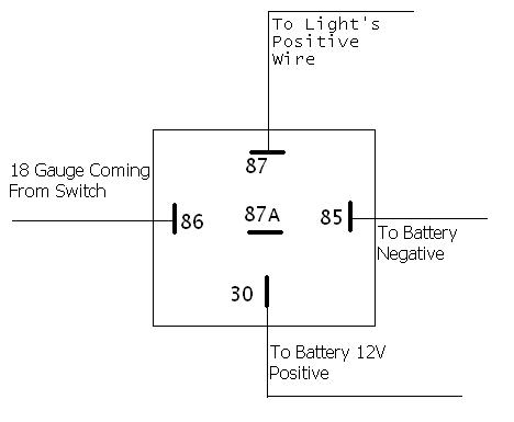
Now, on to actually doing the wiring. First thing you�ll need to do is decide on a place to mount the relay. Closer to the battery the better. After you�ve decided on a place, start wiring the relay. I drew a picture of what each connection on the relay should be connected to, and it�s at the bottom of the page.
The terminal labeled 87 and 87a, that�s where the positive leads for the lights connect to. You'll want to put each light on its own positive terminal. The terminal labeled 12V Positive will be connected with 10 gauge coming from the positive terminal on the battery. Before this wire reaches the 30 terminal on the relay, you need to place your inline fuse holder on the wire, so the positive wire is protected. It can even be connected right to the battery, and then after the fuse, run to the 30 terminal. The terminal labeled 12v negative will be connected with 10 gauge coming from the negative terminal on the battery. The terminal labeled with the wire coming from the switch, will obviously be connected to the wire that comes out of the switch.
Wiring the switch is pretty simple. The most difficult part of it is getting the wire into the cabin. You�ll want to use speaker wire, which has a negative and positive labeled sides. There�s a rubber grommet that a lot of factory wiring runs through on the driver side firewall, about 8 inches down, from the top. I�ve never seen this, but I�ve been told it�s there and seen pictures. I ran mine through the driver side door jamb and through the rubber boot connecting the door to the body. After you manage to get the wire through to the cabin from the engine compartment, run it to where you want your switch mounted. Connect each side of the wire to its own terminal on the switch, it doesn�t matter which. Go ahead and mount the switch after it�s wired. Make sure the two wires aren�t touching each other, use electrical tape to ensure that. Now, with the end that�s in the engine compartment, you�ll connect one side of it to the 86 terminal on the relay. The other side of the wire will be connected to the positive terminal on the battery. It can be tied in with the other positive wire�s ring terminal.
Now, each 10 gauge coming from the relay will go to it�s own light. Run it somewhere that it wont stand out, or interfere with anything else in the engine compartment. I chose to run mine through the holes that the headlamp goes through, there�s enough space to fit another wire between it and the foam around the bulb. Then from there, I went down and under the bumper cover, and drilled a small hole for the wires to come through. Your off road lights should have a metal wire cover thing that you�ll later connect to the bumper cover.
Connect the negative side of the light's wire to a run of 10 gauge. Find a solid ground point, grind any paint off, and ground here. If you have enough wire, you can also run this directly to the battery's negative. To run it directly to the battery, you'll need more wire, and two more ring terminals to connect to the battery.
Each light will have a little metal wire cover, which after all the wires are connected, you can pull the wires down to under the bumper cover and then pull the metal cover so one or two ridges are pulled through, just to ensure it�ll stay there and not have wire hanging out.
With every wire connection you make, you need to wrap it well in electrical tape to ensure they wont ground out or come disconnected. If you aren�t soldering your connections, then the male and female disconnects are to be used. Crimp the wires very tightly when using them, and make sure to wrap them with electrical tape.
Any questions or comments can be directed to me at [email protected]