Brake and Running Light Kill Switches
This will be a detailed write up on how to wire in kill switches to all of the brake and running lights. This is most definitely illegal, so do it at your own risk, I�m not responsible for your actions.
What you�ll need:
Lots of time
A lot of 16 gauge speaker wire, 100 feet should suffice
Wire stripper or scissors, something to strip wire with
Soldering iron and solder
Electrical tape
Test light
Toggle switches that can handle 6 amps, SPST (single pole single throw)
Tools to disassemble your vehicles interior
Zip ties
The first thing you need to do is determine how many brake and running lights there are on the back of your vehicle. There should be at least one running and one brake bulb in each tail light, and several in the center mount brake light. Every vehicle is different, but figure this out and take notes on a notebook to keep track.
The next thing you need to do is trace wire. You need to track down the wire coming from each bulb, and see if for example the left and right running light stem off a common wire at some point. If not, no problem. There may also be double filament bulbs, in which case they are both a running and brake light. The running light part of it will usually stem off another running light�s wire in the same assembly. The idea is to use as few switches as possible. It would be very convenient to tie everything into one switch, but then all the brake and running lights would all function as one.
After you�ve found the wires that lead to the assemblies, and any possible wires that split and go to two different bulbs to save on using extra switches, you�ll need a test light to test wires. Use a box cutter knife, or something to cut off a small piece of insulation from the suspect wires. Turn the running lights on, but make sure none of the wires are touching. Put the ground part of the test light on a good ground, and one by one go through the wires and find all the running light�s positive wires. Take note at what happens with each wire for later reference.
After you�ve found the running lights, repeat the process for the brake lights. Turn the running lights off, and have someone hold their foot on the brake pedal. Take note at which test positive for when the brakes are on. Do this whole process for both tail lights and the center mount brake light.
Make sure to tape up all of your cut wires so there�s no exposed wire any where. Like always, every vehicle is different, but count how many running light wires you found, and how many brake light wires you found. My Grand Cherokee had 6 total. 4 brake wires, and 2 running wires. This is how many switches you�ll need if you cannot find any common wires for more than one bulb. If you�re ordering from the internet, order them asap. If you�re buying them locally, buy them now because your vehicle is only going to get more disassembled as we go along.
You�ll also want to make sure you have all the other supplies needed before you really dig into this project. Having enough wire is crucial. It�s a huge inconvenience to not have enough wire when you�re nearly completed with the interior taken apart.
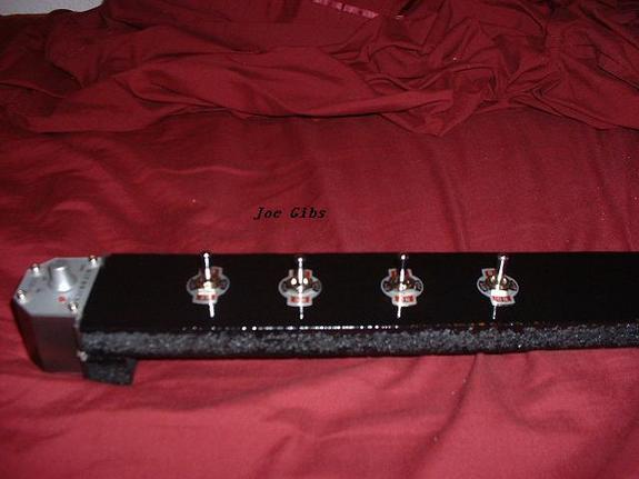
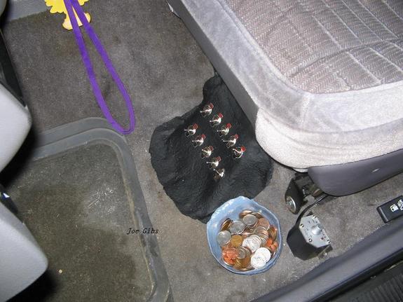
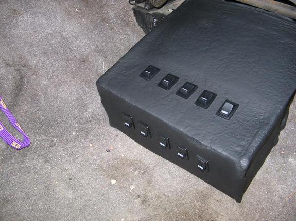
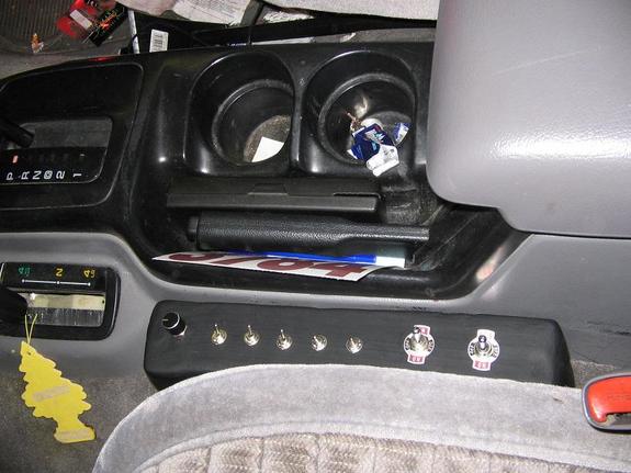
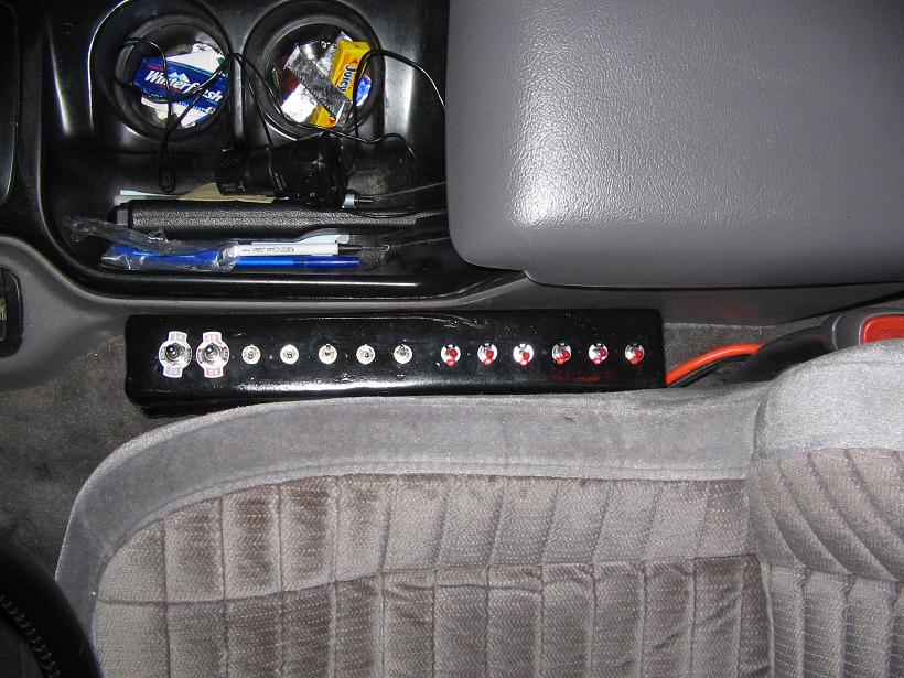
At this point you�ll want to decide where you�re going to want your switches to be mounted. There�s a gap between the seat and center consol of my jeep, so I made a fiberglass switchboard and mounted it there. As for other locations, I�ve done things like drilling into factory panels, fiberglassed switchboards to the floor almost underneath the seat, wood cut to fit a specific place. See pictures below for some ideas.
After you�ve decided on a location, take a piece of string and test to see how many feet of wire you�re going to need. Go from each assembly to where the switches will be mounted. Make sure to account for the bends and routes they wires are going to need to take to go under the carpet without being noticed. Don�t run them on both sides of the vehicle, pick a side and run them all together to the front, so account for having to go from say the passenger to the driver side, then all the way to the front. After you�ve figured how many feet you�ll need, add on another 10-15 feet to account for slack and un-accounted for bends and turns.
Make sure to use 16 gauge to ensure the wire is large enough to handle the current being passed. If your wire is too small, it will heat up and cause un-needed resistance. It could also potentially cause a fire. There is however a factory fuse on the wiring, so it shouldn�t be too big of a concern.
You can now start cutting into the wire. In a spot that has plenty of slack on both ends to strip, and then solder on new pieces, cut each wire in half. For example, before the assemblies, there�s a 6� stretch of wire, cut right in the middle of it so you have plenty to work with. DO NOT cut right next to the bulb socket or any wiring harness. After you have all your wires cut, do a test with both the running and brake lights. Nothing in the back should light up. If anything does, you didn�t find all the wires with the test light.
The wire you have is probably marked positive or negative, it doesn�t matter which is soldered to each end of the factory wire. Measure out how long each piece will be from the spot it�s being soldered in to where the switch will be mounted, and then cut the wire from the spool to length. Leave an extra foot or two just incase. Go ahead and solder the two ends of wire onto the cut factory wire, and label the ends to which wire you cut into for later reference. Make sure to tape all soldered connections. Do this with all the wires, all running and brake wires, from both the tail lights and the center mount brake light.
After all your wires are cut, and have the new lengths of wire soldered in, run them all to a common starting point in the rear that they�ll all be bundled together and run to the front of the vehicle. Use a zip tie every 6� to make sure the bundle is kept tight. If this bundle wont fit under the carpet without being noticed, lay it out flat, and zip tie every foot or so, but loose enough to not bunch it up. As the bundle is moving towards the front, you�ll want to zip tie to other factory wire bundles or anything to hold your wire in place in the route you want it to take. As a last resort, duct tape can be used to hold it in place until the carpet or panels are put back in place.
Now you should have all your wires run to the front of the vehicle and to the point you want to mount your switches. On the back of your switches, there should be two connections. Each speaker wire has a positive and negative, positive goes to one connection on the switch, negative goes to the other connection. Doesn�t matter which goes to which. Do the same for all the wires. Connect the wires to the switches before they�re mounted. After they�re connected, go ahead and mount them to you chosen location.
Not many people would have much of a use for this, but some people might think it�s something cool and cheap to do.
Any questions or comments can be sent to [email protected]