2.1 Refractory Materials
The
term refractory means resistance to heat. Refractory
metals are a specific group of metals having melting points over 1650°C.
In fact, precious metals also have high melting points but this is not as
important as their financial value. The
most important metals in the refractory metal group are zirconium, molybdenum,
tungsten, niobium and tantalum. From
a commercial point of view these are the most widely used because of their
stability at elevated temperatures. Applications
are limited to non-oxidising conditions where the load bearing requirements are
not too severe.
Since
metals are of limited use, compounds of the refractory metals have been
investigated and developed such as carbides, borides, nitrides and aluminides as
well as hybrid materials such as the cermets and metals reinforced with
refractories. In general, these
‘new’ materials are brittle with poor thermal conductivity and high
expansion offering poor resistance to thermal shock.
The requirements that have to be met by hard metals or ceramic high
temperature materials will vary considerably within large limits dependant upon
the intended application. Creep
resistance and stress rupture strength are probably the most important amongst
the mechanical requirements and high strength to weight ratio materials will
obviously be favoured.
2.2
Transition metal carbides
The
carbides of the transition metals in Groups IV - VI have extremely high melting
points (Table
1) and are therefore referred to collectively as the “refractory carbides.”
In addition to their stability at high temperatures, these compounds are
extremely hard (Table 2), finding industrial use in cutting tools and
wear-resistant parts. Their hardness is retained to very high temperatures, and
they have low chemical reactivity – they are attacked only by concentrated
acid or base in the presence of oxidising agents at room temperature, and retain
good corrosion resistance to high temperatures. The refractory carbides are
strong, with Young’s modulus values – a measure of elastic deformation
resistance – rivalling those of silicon carbide
(SiC) at room temperature. In addition, they have good thermal shock
resistance and good thermal conductivity, permitting heat to be drawn away from
the working surface of the tool. This gives them a benefit over other refractory
materials, which do not conduct heat as well. (Table 3).
|
Metal |
(oC) |
Carbide (MC) (oC) |
Carbide (MC) (oC) |
|
Ti |
1677 |
3067 |
2940 |
|
Zr |
1852 |
3420 |
3420 |
|
Cr |
1900 |
1810 (Cr3C2) |
|
|
V |
1917 |
2648 |
|
|
Hf |
2222 |
3928 |
3820 |
|
Nb |
2487 |
3600 |
|
|
Mo |
2610 |
2600 |
|
|
Ta |
2997 |
3983 |
|
|
W |
3380 |
2776 |
|
|
Phase |
Structure |
Lattice (Å) |
Young’s
Modulus x
106 psi |
Micro-hardness
(kg/mm2) |
Coefficient
of Thermal Expansion x 10-6 |
Color |
|
TiC |
Rocksalt |
4.328 |
39-67 |
2900 |
7.4 |
Grey |
|
ZrC0.97 |
Rocksalt |
4.698 |
56 |
2600 |
6.7 |
Grey |
|
HfC0.99 |
Rocksalt |
4.640 |
46-61 |
2700 |
6.6 |
Grey |
|
VC0.97 |
Rocksalt |
4.166 |
63 |
2900 |
-- |
Grey |
|
NbC0.99 |
Rocksalt |
4.470 |
49-74 |
2400 |
6.6 |
Lavender |
|
Material |
Melting Point (oC) |
Micro-hardness (kg/mm2) |
|
SiC |
2300
|
2580 |
|
C,
diamond |
3800
|
7600 |
|
Al2O3 |
2050 |
2080 |
For
high-temperature applications, the carbides are used as pure-material sintered
parts or in a composite such as the Co/Mo/W/carbide
sintered composite. These materials outperform the standard alloys and so-called
“super-alloys” in such applications as rocket nozzles and jet engine parts,
where erosion resistance at temperatures in excess of
2500oC is crucial. TiC1-x and VC1-x in
particular maintain high strengths up to 1800oC and therefore can be
used as high temperature structural materials, provided that internal and
surface flaws, such as stress cracks and pores introduced during fabrication and
sintering, are removed. Such defects lead to high room-temperature brittleness;
plastic flow relieves internal stresses caused by defects and leads to reduced
brittleness at high temperatures. Plastic deformation occurs particularly via a
mechanism of dislocation glide along {111} planes.
It
must be noted that there is some variation in the literature with respect to the
reports of assorted mechanical and thermodynamic properties of the refractory
carbides. The transition metal carbides show a range of non-stoichiometries (where
stoichiometry is the ratio of cation to anions as specified by the chemical
formula) and possibilities for vacancy ordering, so the precise phases
being tested for a given property are often unclear. Furthermore, small
concentrations of oxygen present as metal oxides are famously difficult to
remove – or even detect – and can be expected to affect the properties of
the material.
Tungsten
carbide (WC) is the most commonly used monocarbide.
Approximately two third of tungsten
production in the United States is used to make tungsten carbide for use in
cemented carbide manufacture. Fabrication as a “cemented carbide” tools for
cutting steel, is essentially by a diffusion process.
Tungsten powder is carburised and the tungsten carbide powder is
bonded in a metal matrix, usually cobalt. Cobalt is used because it wets the
carbide particles and therefore behaves as a good binder without having
significant ability to dissolve the carbide, so that the carbide is left pure in
the bound form. However, pure WC-Co cemented carbides tend to weld locally with
the steel being cut. TiC, TaC, and NbC are often used in conjunction with WC
because TiC locally forms a layer of TiO or TiO2 which protects the
tool from wear, and TaC and NbC which
raise the melting temperature and oxidation resistance of the tool.
The
melting points of the mixed-metal carbides outperform those of the pure-metal
carbides, as well. Samples prepared by vacuum reduction of the mixed oxide
powders at 2000oC, followed by sintering at 2200oC and
2500oC in good vacuum were tested for their melting behavior. 8TaC.ZrC and 4TaC.HfC
had melting points 3890oC and 3990oC, respectively,
somewhat higher than those of the pure-metal carbides (measured at 3470, 3750,
and 3840oC for Zr, Hf, and Ta carbides, respectively). The higher
melting points in the mixed-metal carbides were attributed to composition
changes due to the selective evaporation of carbon during melting.
Mixed-metal
carbides have been examined for their melting point and hot-hardness behaviour
as well. The hardness arc-cast or zone-melted samples of (Ta0.8Hf0.2)C1+x
was tested (by indentation using diamond or B4C tips) and compared
with that of the similarly-prepared pure-metal carbides TaC1-x and
HfC1+x over the temperature range 800 - 2000oC.
In all cases the hot hardness decreased with increasing temperature. For
temperatures up to 1400oC the hardness order increased as HfC1+x
< (Ta0.8Hf0.2)C1+x < TaC1-x,
but over 1400oC the mixed carbide began to outperform the tantalum
carbide. Hardness varied from 600 kg/mm2 to 1500
kg/mm2 over the temperature range tested.(
Koester, R. D.; Moak, D. P. J. Am.
Ceram. Soc. 1967)
 2.2.1.
Structures of Transition Metal Carbides
2.2.1.
Structures of Transition Metal Carbides
Most
of the transition metal mono-carbides form in the B1
(NaCl) or rocksalt crystal structure. A
unit cell for this structure is generated from a face centred arrangement of
anions (a negatively charged non-metallic ion) with one cation (a positively
charged metallic ion) situated at the cube centre and one at the centre of each
of the 12 cube edges. Therefore the rocksalt crystal structure may be thought of
as two interpenetrating fcc lattices, one made up of cations and the other made
up of anions. The co-ordination number for both cations and anions is 6.
These
materials contain ions of at least two kinds and therefore defects, such as
interstitials or vacancies for each kind may occur.
It is of course unlikely that there would be anion interstitials because
the anion is relatively large and would introduce substantial strain on the
surrounding ions if forced into an interstitial position.
The atoms exist as charged ions and when defect structures are being
considered, conditions of electroneutrality must be considered.
Because of this, defects in ceramics do not occur in isolation but in
defects pairs such as the Frenkel defect and the Schottky defect.
The Frenkel defect involves a cation vacancy and a cation interstitial
pair, whereas the Frenkel defect involves a cation and anion vacancy pair.
The ratio of cations to anions is not altered by the formation of either
the Frenkel or the Schottky defect and if no other defects are present the
material is said to be stoichiometric. Stoichiometry
is defined as the state for ionic compound where there is an exact ratio for
cations and anions predicted by the chemical formula.
A ceramic compound is nonstoichiometric when there is any deviation from the exact ratio.
The
shortest metal -to -metal (M-M) distance is about 30% greater in the rocksalt
structure (B1) carbide than in the
pure metal for the Group IV and V carbides, but drops to less than 10% greater
for the Group VI or VII carbides. At 100% site occupancy, the stoichiometry of
the carbide is MC1.0, though this situation is rarely realised. The
concentration and ordering, if any, of the vacancies that result from a
non-stoichiometric metal-to-carbon (M-C) ratio have a great effect on the
thermodynamic, mechanical, electronic, and magnetic properties of the metal
carbides. However, the details of these effects are a matter of some debate in
the literature, due to the difficulties inherent in synthesizing pure compounds
and in measuring the exact details of the crystal structure of a given sample.
The metal carbides share many characteristics with the metals themselves, having
(the same slip systems) a plastic deformation
like as the fcc metals which, while lowering the high-temperature hardness,
protects parts fabricated from the carbides from catastrophic failure in
response to stresses.
2.3.
Group IV - V Carbides
2.3.1.
General Trends
Approximate
preparation of the transition metal carbides is straightforward, but ensuring a
given stoichiometry and purity against oxygen contamination is famously
difficult. Variations in the quantity of vacancies on the carbon (or, less
frequently, the metal) lattice, as well as variations in the amount of dissolved
oxygen, lead to a wide range of claims regarding even basic thermodynamic,
mechanical, and electromagnetic data for the early transition metal carbides.
Removal of the Oxy-carbide phases, which can be considered to be solid solutions
of MO and MC, depends on the partial pressure of CO over the sample to be
purified. At the high-carbon end of the stoichiometric range, Equation 2.1 leads
to additional dissolved oxygen in the lattice if CO is removed. At the
low-carbon end, Equation 2.2 occurs independently of the CO partial pressure.
Thus if excess graphite is present, a high CO partial pressure leads to more
nearly stoichiometric carbide as Equation 2.1 is forced left; but the success of
this approach in purifying a given metal carbide depends on the stability of the
oxycarbide, the annealing temperature and time, and, clearly, the partial
pressure of carbon monoxide.
MxOy
+ C (dissolved in MC) = MO (dissolved in MC) + CO (g)
eqn.2.1
MxOy
+ M (dissolved in MC) = MO (dissolved in MC)
eqn. 2.2
Group
IV carbides are difficult to purify without melting; heating up to 2000oC
will result in increased oxygen contamination if the vacuum is not better than
10-6 torr. Moreover, as noted in the previous section, few
straightforward chemical methods exist for finding the oxygen level in the Group
IV carbides MC1-x bulk materials; none are reliable. The Group V and
VI carbides purify readily at temperatures over 1800oC.
Slow
diffusion of carbon in all of the refractory carbides results in stoichiometry
gradients which are difficult to detect in bulk materials but which may
compromise the material strength, hardness, and high-temperature behaviour. The
lattice parameter and the sharpness of the XRD pattern can give some rough
indication of the homogeneity, however.
Group
IV metals tend to form in a single cubic phase with a limiting stoichiometry
near MC1.0, but which normally varies from MC0.5 to MC0.97
depending on the synthesis conditions. Group V metals form an M2C
phase in addition to the monocarbide. The composition range of the M2C
phase is narrow at room temperature, with decomposition into the cubic phase
plus liquid at high temperatures. The V-C system has a cubic phase extending to
MC0.88, while NbC and TaC approach MC1.0 and melt
congruently even at carbon-deficient stoichiometries. The Group VI metals have a
more complex M-C phase diagram, forming a number of distinct compositions. The
chromium carbides behave uniquely, while the Mo-C and W-C systems have common
features, with the MC and M2C phases stable at high temperatures.
(Table 4) The trends in melting points indicate that the Group IV, V, and lower
two Group VI metals have strong M-C and M-M bonds, distinct from the Groups IA -
IIIB metals, which form acetylenic M-C bonds, and from the Groups VIII - IIB
metals, which form unstable carbides, if at all.
Removal
of bound carbon causes the lattice parameter to decrease in most of the
refractory carbides, but to increase in TiC and ZrC. The behaviour of HfC on
decrease of the lattice carbon-to-metal ratio is uncertain due to the variation
in this behaviour among reports. For several metal carbides, the variation of
lattice parameter with carbon content is linear. Removal of carbon from the
lattice also is associated with reductions in hardness, at least for the Group
IV carbides. Dissolved oxygen lowers the lattice parameter in Group IV carbides,
while it increases it in Group V carbides, and has an uncertain effect for
carbides of Group VI metals. The effect of oxygen contamination on mechanical
properties is not clearly reported in the literature.
The
refractory carbides show high chemical resistance but will react under certain
conditions. At high temperatures, the high-carbon compositions form hydrocarbons
in the presence of hydrogen. The reactions with oxygen have been indicated above
(Equations 2.1, 2.2), and are complex. The carbides will form the nitrides at
high temperatures and in the presence of N2, NH3, or N2/H2
mixtures; however, the cubic carbides and nitrides are completely miscible.
2.3.2
Group IV
The
conversion of TiO2 to TiC occurs via the intermediates Ti3O5,
Ti2O3, and TiO in the temperature range 1000 - 1500oC.
The carbide closest to TiC1.0 forms at 1600-1700oC under
1-10 torr of CO. Titanium hydride and carbon form TiC1.0-x after 1
hour in vacuum at 1200oC. TiC has also been formed by heating a
tungsten wire or carbon filament in an atmosphere of TiCl4, H2,
and hydrocarbon, or by reaction of CaC2, TiCl4, and H2
at 800oC (CaC2 and CaCl2 are removed by washing
with water after the reaction is complete). The last traces of oxygen are
difficult to remove, and have a significant effect on the material properties.
Later heating may recontaminate even a “pure” sample of titanium carbide if
the vacuum is not sufficiently good; a non-protecting, non-adherent TiO2
(anatase) layer forms at about 450oC. The Ti-C system has one cubic
compound of formula TiC, although other phases have occasionally been claimed.
TiC is metallic and gray, and is stable to most concentrated acids or bases. It
will dissolve completely in HNO3 and combinations of HNO3
with HCl (aqua regia), HF, and H2SO4.
The
reduction of ZrO2 proceeds via Zr2O3 and ZrO to
the carbide between 950-1200 oC. It has also been formed using ZrH
plus graphite or from ZrCl4 in the presence of hydrogen and
hydrocarbon vapour. Attempts to remove oxygen completely are generally
unsuccessful except under melting conditions. “Pure” ZrC heated at
temperatures under 1800oC tends to gather oxygen up to several
percent. The Zr-C system contains one cubic compound, ZrC, and the lattice
parameter varies with oxygen contamination noticeably at levels of 1000 ppm. ZrC
is somewhat more susceptible to acid attack than is TiC and oxidises rapidly
above 500oC.
HfO2
forms an oxy-carbide of constant composition between 1743 - 2033oC
and under 70-1000 torr of CO, with Hf2O3 forming at
1000-1200oC and the HfC-HfO solid solution between 1300-1800oC.
HfC forms a carbon-deficient lattice between 1800 - 2000oC, but can
be made stoichiometric by repeated heating at 190oC. HfC has also
been formed from HfCl4 + H2 + CH4 in the
presence of a hot tungsten wire and from hafnium hydride and carbon. It is one
the most difficult carbides to rid of its oxygen, only becoming “pure” when
melted or heated at temperatures in excess of 2500oC in good vacuum.
The Hf-C system has one cubic phase HfC, but the composition can range to a low
of HfC0.52. Its melting point increases with increasing carbon
content up to a maximum, then HfC forms a eutectic with carbon. There has been
no study of lattice parameter variation with either oxygen or carbon content.
2.3.3. Group
V
Heating
V2O5 or V2O3 with carbon for two
hours at 1800oC in 1-10 torr of CO has formed vanadium carbide. V2O5
begins reacting with carbon at 435oC, and the oxygen concentration is
relatively easily reduced to below detectable limits by higher-temperature
treatments or by the reaction of vanadium metal or hydride with carbon. Loss of
vanadium at high temperatures and low carbon content presents a difficulty, but
near-saturated VC can be heated to 2000oC without loss of vanadium.
The carbide has been made by treatment of VCl4 in an atmosphere of
hydrogen and methane at 1500 - 2000oC. The two main phases are cubic
VC, available over the range VC0.78-VC1.0, and the
hexagonal beta-V2C, available for C/V atom ratios of 0.4-0.5 between
approximately 1500 - 2000 oC, but presenting a very narrow range of
stable compositions at room temperature. Reports of V5C and V4C3
have been discredited. VC will react with dry HCl gas at 750oC to
produce VCl2, methane, and hydrogen, and has a high rate of oxidation
in air, with powdered VC and V2C being attacked slowly by air even at
room temperature. V2C is soluble in hot 50% HCl solution, leaving a
carbon residue, but VC is inert under these conditions; both of the vanadium
carbides are attacked by concentrated nitric, sulphuric, and perchloric acids.
Niobium
oxide begins to react with carbon at 675oC, forming NbO2
and NbCx below 1200oC and forming an NbCxOy
solid solution between 1450 and 1500oC. Pure NbC is accessible by
heating the metal and carbon powders directly, but high temperatures and heating
times are required to complete the reaction and drive off oxygen and nitrogen
contaminants. The conditions are made less stringent by the presence of an H2
atmosphere. NbCl5 heated in the presence of hydrogen and methane
forms the pure carbide at 900 -1000oC. The Nb-C system has the cubic
phase NbC and two crystal forms (alpha, room temperature, with a very narrow
composition range and beta, existing between 2300-3000oC and over the
C/Nb ratio range 0.4-0.5) of Nb2C. A third, zeta phase of Nb2C
(C/Nb range 0.5-0.7) has been suggested to exist on the basis of a single weak
powder pattern line, but has not been verified. The lattice parameter increases
as the C/Nb atom ratio approaches unity, and is increased as well by the
presence of oxygen and nitrogen. NbC is inert even to boiling aqua regia but
will dissolve in HNO3/HF mixtures; it is severely corroded in air at
temperatures above 1100oC. Its colour ranges from grey (NbC0.9)
to lavender (NbC0.99).
The
tantalum carbide system is relatively easy to free of oxygen impurities, but due
to the slow rate of carbon diffusion it tends to have in-homogeneities in its
bulk composition. Evaporation of carbon at temperatures above 2400oC
renders the use of high temperatures to establish a uniform composition
problematic. Reaction from the elements in vacuum begins at approximately 1000oC
but is slow to reach completion. Use of hydrogen or methane atmospheres
increases the reaction rate but requires a post-synthesis vacuum-annealing step
to remove dissolved hydrogen. TaC cannot be made from TaCl5 in a
hydrocarbon/hydrogen atmosphere due to the formation of metallic tantalum, but
has been made with varying success by heating Ta wire in methane. Arc melting
tends to produce C-deficient, in-homogenous carbides. The Ta-C system has the
cubic phase TaC and a hexagonal compound Ta2C (actually the C6
anti-CdI2 structure type due to ordering of the carbon atoms) with a
transition near 2000oC. A phase has been claimed at 2000 - 3000oC
over the C/Ta atom ratio 0.70-0.75 but its existence remains a point of debate.
The cubic phase persists over a wide temperature and composition range, possibly
as low as TaC0.58 and verified down to at least TaC0.74.
The composition TaC0.89 is the highest-melting substance known. Very
small amounts of carbon (Ta64C) result in a tetragonal distortion to
the normally bcc Ta parent lattice. The TaC lattice varies linearly with
composition, with the equation C/Ta = -25.641 + 5.9757a. It is grey and metallic in appearance up to about TaC0.85,
then becomes increasingly brown with rising carbon content until the golden TaC0.99
is reached. It is the most acid-stable of the refractory carbides, dissolving in
a nitric/hydrofluoric acid mix, and reacts with pure oxygen above 800oC.
Loss of carbon results from lower-temperature reactions with oxygen in air.
Table 4. Range of Melting Points for Group IV-VI Carbides
|
Metal |
Element (oC) |
Maximum (oC) |
In the presence of C (oC) |
Atom Ratio at Maximum value |
|
Ti |
1668 |
3067 |
2776 |
0.8 |
|
Zr |
1855 |
3420 |
2850 |
0.83 |
|
V |
1888 |
2700 |
2700 |
0.85 |
|
Cr |
1915 |
1875 |
1875 |
0.68 |
|
Hf |
2222 |
3950 |
3180 |
0.95 |
|
Nb |
2467 |
3600 |
3300 |
0.82 |
|
Mo |
2620 |
>=2580 |
258 |
0.72 |
|
Ta |
3014 |
4000 |
3400 |
0.88 |
|
W |
3410 |
>=2780 |
2780 |
0.75 |
2.4.1. Tantalum
Tantalum is a grey, heavy, and very hard metal. When pure, it is ductile and can be drawn into fine wire, which is used as a filament for evaporating metals such as aluminium. Tantalum is almost completely immune to chemical attack at temperatures below 150oC, and is attacked only by hydrofluoric acid, acidic solutions containing the fluoride ion, and free sulphur trioxide. Alkalis attack it only slowly. At high temperatures, tantalum becomes much more reactive. The element has a melting point exceeded only by tungsten and rhenium. Tantalum is used to make a variety of alloys with desirable properties such as high melting point, high strength, good ductility, etc. Tantalum has a good "guttering" ability at high temperatures, and tantalum oxide films are stable and have good rectifying and dielectric properties
|
Name |
Tantalum |
|
Symbol |
Ta |
|
Atomic number |
73 |
|
Atomic weight |
180.9479 (1) |
|
Group in periodic table |
5 |
|
Period in periodic table |
6 |
|
Block in periodic table |
d –block |
|
Electron Configuration |
[Xe]6s24f145d3 |
Isolation of tantalum is very complicated. Usually niobium and tantalum are both contained in tantalum bearing minerals. It is difficult to separate niobium and tantalum since they are chemically so similar. Tantalum can be extracted from the ores by fusing the ore first with alkali, and then extracting the resulting mixture into hydrofluoric acid. Recent methodology involves the separation of tantalum from these acid solutions using a liquid-liquid extraction technique. In that process tantalum salts are extracted into the ketone MIBK (methyl isobutyl ketone, 4-methyl pentan-2-one) .The niobium present in tantalum mineral remains in the hydrofluoric solution. After conversion to the oxide, metallic tantalum can be made by reduction with sodium or carbon. Electrolysis of molten fluorides are also used.
Separation of tantalum from niobium requires several
complicated steps. Several methods are used to commercially produce the element,
including electrolysis of molten potassium fluorotantalate, reduction of
potassium fluorotantalate with sodium, or reacting tantalum carbide with
tantalum oxide.
Tantalum
carbide of the chemical formula TaC, with a theoretical carbon content of 6.23%,
is a metallic powder of a dark light-brown colour. The colour in influenced by
nitride admixtures and very thin oxide films. Pure crystals isolation from the
metal bath have a gold lustre. Preparations described as grey powder are
probably Ta2C.
Tantalum
carbide in only slightly soluble in acids .It burns in air with a bright flash.
The density of TaC was given by Friederich
and Sittig as 13.96 g./cm.3, while Mckenna”s
preparations, which was formed in a
aluminium bath, had the density 14.48 g/cm.3, which is close to the
X-ray density of 14.53 g. /cm.3.
According
to Friederich and Sittig the Mohs hardness of TaC is 9
to 10 while Styri and Foster
and co-workers give a Brinell hardness of 840 and a Knoop hardness of
840 kp/mm2 The micro hardness obtained by Kieffer and Kolbl using a
load of 50g was 1,88 kg/ mm.2. The
same value has been measured by Hinnuber using a 20g. load. The modulus of elasticity is,
according to Koster and Rauscher 29,500 kg./mm2
(41.5*106 psi). The tensile strength of vapour-deposited TaC wire at room
temperature was determined by Becker
and Ewest as 2000-4000
psi.
The
carbide Ta2C melts at 3400°C with decomposition, according to Ellinger . The mono carbide melts, at
4730 –4830°C with decomposition, according to Friederich and Sittig
The
specific elastic resistivity of TaC is 200 microhm-cm(µW)
according to Friederich
and Sittig , 100 microhm-cm according
to Moers , and 170 microhm-cm
according to Andrews , while recent
measurements reported by Schwarzkopf and
Sindeband ,
give a values of only 30 microhm-cm . The variation of resistivity
with temperature was measured by Becker
and Ewest ,. According to Meissner and
co-workers , the mono carbide becomes super conductive between 9.5
Kelvin and 7.3 Kelvin.
Haddan, Goldwater and Morgan measured
the thermionic emission of TaC at 2300°C. The emission was 2.8 times smaller
than that of metallic Ta. The values obtained did not indicate any practical
possibilities for the use of TaC as emitter. The same authors, as well as Morgan
, determined the spectral emissivity of TaC coatings and found the value of
0.67 at 0.655 micron.
2.4.4. Phase diagram of
the system Ta-C
On
the basis of microscopic and X –ray investigations and of melting point
determinations on tantalum carbide specimens produced by vacuum-sintering,
fusion, or surface carburization of tantalum, Ellinger
established a phase
diagram of the system tantalum-carbon, the tantalum-rich corner of which is
shown in Fig 3. There exists two defined compounds, Ta2C (3.21%of
C),with a melting point at about 3,400 degree Celsius, and TaC (6.23% of C) with
a melting point at about 3,800
degree Celsius . At 0.6% of C, Ta forms a eutectic with Ta2C at a
temperature of about 2800 degree Celsius, Ta2C being able to dissolve
in 0.2% of Ta. An appreciable solubility of carbon in tantalum is not
observable. The melting point of TaC of about 3800 degree Celsius is lowered by
the absorption of carbon to a second eutectic at 10% of C and 3300degrss
Celsius. At 3400 degree Celsius TaC is able to dissolve up to 1.2% of Ta, as had
been surmised by Burgers and Basart
. While TaC has a cubic face-centred lattice,
Ta2C, first described by Burgers
and Basart has a
hexagonal close-packed structure corresponding to a c/a ratio of 1.59.
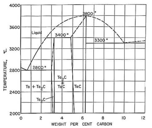
Fig 1
(Phase Diagram of the system Ta-C)
Like
W2C, a2C occurs, according to Burgers
and Basart in two
allotropic modifications, a-Ta2C
and b-Ta2C. Examinations of the surface
of Ta wires, which had been carburised from the gaseous phase under controlled
conditions, showed the b-Ta2C
modification. After pulverisation of the wire, however, the X-ray diagram
exhibited the lines of a-Ta2C.
Whether b-Ta2c occurs only at the surface of the wire
or is transformed into a-Ta2C
on pulverizing remains an open question.
On
rapid cooling of burned out TaC wires from above 2530 degree Celsius, a-Ta2C
appears (at variance with W2C which occurs as b-modification
after rapid cooling). Since a weakening of certain lines in X-ray diagram is
observed rather than their disappearance during the formation of the two
modifications,it is to be assumed that transition is continuous. Ellinger
who studied a number of
Ta2C-bearing preparations, was unable to demonstrate the existence of
different modifications.
Table 4. Properties
of tantalum monocarbide in the homogeneity range
|
Formula |
DH298 kJ/mole |
DH298 kJ/mole |
DS298 J/mole
.deg |
DS298 cal/mole.deg |
DF298 kJ/mole |
DF298 kcal/mole |
Micro-hardness (MN/m2) |
Specific Electrical Resistivity (mW
.cm) |
|
TaC0.60 |
78.4 |
18.7 |
2.01 |
0.48 |
77.9 |
18.6 |
11110 |
134.0 |
|
TaC0.65 |
- |
- |
- |
- |
- |
- |
- |
114.0 |
|
TaC0.70 |
90.1 |
21.5 |
1.80 |
0.43 |
89.7 |
21.4 |
- |
126.0 |
|
TaC0.75 |
- |
- |
- |
- |
- |
- |
13600 |
110.8 |
|
TaC0.80 |
106.8 |
25.5 |
2.10 |
0.50 |
106.4 |
25.4 |
- |
- |
|
TaC0.85 |
- |
- |
- |
- |
- |
- |
14460 |
41.2 |
|
TaC0.90 |
132.8 |
31.7 |
3.35 |
0.80 |
132.0 |
31.5 |
- |
- |
|
TaC0.95 |
- |
- |
- |
- |
- |
- |
14700 |
34.0 |
Tantalum carbide in the form of wires has been
proposed for use as wound filaments in incandescent lamps. The low strength of
tantalum carbide wires however is prohibitive for general use. For similar
applications, protective coatings of tantalum carbide and rhenium or tungsten
wires have been suggested. High-sintered tantalum carbide tubes have been used
to reach extreme high temperatures as required, e.g., for the determination of
the melting point of high-melting hard metals.
Tantalum carbide is of practical importance in the production of cemented multicarbide hard metals. In machining-tool materials, TaC, like TiC, reduces the tendency of welding between steel chips and tool material and thus the so-called cratering, which is due to such welding, and the subsequent separation of the welds.