Our starting points in design were directly inspired by Scott Teige's model, this being the trebuchet with which we had the most familiarity, and the Discovery channel trebuchet documentary. We used the general shape of the trustle on Scott's model, but on a larger scale. Also, Scott's trebuchet used a counterweight design known as a propped counterweight, whereas we decided to use a fixed counterweight. Another difference arose in that our trebuchet was mounted on wheels, and Scott's trebuchet was stationary. The whole purpose of either having a rolling base or a propped or swinging counterweight is to allow the counterweight to fall in as close to a straight line as possible. However, when a trebuchet is both on wheels and has a swinging counterweight, elements of chaos ensue and degrade the trebuchet's performance
The MacTreb 3.0 trebuchet simulation program, which was obtained from The Algorithmic Beauty of the Trebuchet webpage Cortez, helped us choose starting measurements for various parts of the trebuchet. We played with the variables of the trebuchet in the simulation program until we came up with a design that would throw a range suited well to data taking (roughly 20 to 30 meters). We decided to make the axle height 1.5 meters, and to vary the arm lengths between 1.5 meters and 2.5 meters on the throwing arm side and between .5 meters and 1 meter on the counterweight side. We decided on a counterweight with mass 10 kilograms and a projectile of mass 1 kilogram.
Since we knew our data taking procedure would rely heavily on the use of videos and the Video Point software, we wanted to design a trebuchet that would be optimized for use with video recording. Eric Scott, our Design Consultant (engineer who kept us from screwing up), suggested the use of plexiglass in the frame, for transparency and stability. One of the main problems with analyzing Scott Teige's trebuchet was flucture in the throwing arm during launch. In order to remove this factor from our trebuchet, we chose aluminum as both a lightweight and rigid material. The material of the base was not as crucial, so we simply used a 2 x 4 frame with plywood screwed to the top of it.
Aluminum tubing was readily available in the arm lengths we wanted, so we used tubing 1 1/4" thick and hollow in the center. Using approximation formulas found in the Machinist's Handbook, we were able to estimate the amount of flucture that a 10 kilogram mass would cause in the counterweight side of the arm, and we verified that indeed it would be negligible (7 parts in 1 million.)
The design of the trustle was fairly simple. We settled on one main vertical support on either side, through which the trebuchet's axle would run at the top. Either side would also have two supports going along the length of the base, and another support going along the width. Refer to the Pictures link at the bottom of this page to see pictures from the construction process.
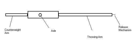
We allowed for variability in the arm lengths by making interchangeable aluminum bars that would fit into either side of a central piece. Here is a diagram:
We were going to achieve variation in the counterweight mass by using lead shot in a bucket as the weight. Thus, we could easily remove whatever amount of mass we wanted to. In practice, this turned out to be extremely ineffective. For a fixed counterweight design, there was pretty much no good solution to keeping the lead shot contained throughout the swing. In the end, we used a 11.8 kilogram (26 pound) lead brick bolted to the arm as the counterweight, deciding to not vary our counterweight.