|
|
|
|
|
|
|
|
|
|
|
|
|
|
|
|
|
|
|
|
|
|
|
|
|
|
|
Installation Instructions
|
|
|
|
|
|
|
|
|
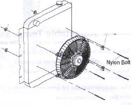
Puller Mode
(as shipped from the manufacturer) Through Core
Mounting Instructions
|
|
|
|
|
|
|
1. Attach
the mounting tabs to the electric fan.
See diagram "A".
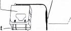
2. Position
the electric fan against the radiator,
and mark mounting hole locations.
3. Pass a
small Phillips screwdriver through the
marked holes, carefully spreading the fins to
allow easy
passage for the nylon bolts. Fit the bolts to the mounting
tabs, and pass the bolts through the shroud holes in the
radiator.
4. Push on the speed nuts until snug.
5. Cut off the end of the mounting
bolts, leaving 1/4" remaining.
|
|
|
|
|
|
Pusher
Mode Through Core Mounting Instructions >1. Remove
retaining clip from motor shaft. •2.
Remove fan blades, flip it over, and re-fit to shaft. Make
sure that pin on shaft is seated into
groove in fan hub. Replace retaining clip.
3. Proceed
with instruction above. Note: some vehicles have ale
condensers or tranny coolers
mounted in front of the radiator. Modifications may be
necessary to accommodate the fan.
|
|
|
|
|
|
|
|
|
|
|
|
Important:
Pusher fans use:
Black wire
is positive (+). Blue/Red wire is negative(-).
|
|
Important:
Puller fans use: Blue/Red wire is positive (+) Black wire is
negative (-).
|
|
|
|
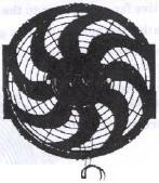
Reverse
wiring
when
installing
#396,
16" S-Blade
|
|
|
|
Reverse
wiring when installing
#396,16"
S-Blad«
|
|
|
|
|
|
|
|
|
Important: Disconnect the battery
prior to wiring any of the products below.
Direct
Connect; (Fan will operate when the ignition is
"on")
1. Attach
the positive fan motor wire to a 12 V positive ignition
controlled source, e.g. fuse box.
Use the 20 amp inline fuse provided for each fan.
2. Attach the negative fan motor wire to
a ground, e.g. negative side of battery, chassis etc....
3. Reconnect battery. • --..
|
|
|
|
|
|
|
|
|
|
|
|
|
|
|
|
|
|
|
|
|
|
|
|
|
|
|
|
|
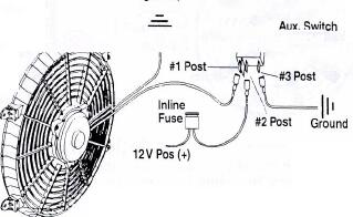
Auxiliary Switch Installation
|
|
|
|
|
|
(Based on
Flex-a-lite part #31148, not included)
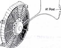
1. Attach
the positive fan motor wire to the #1 post of the switch.
2. Attach
the negative fan motor wire to a ground, e.g. negative side
of battery, chassis.
|
|
|
|
|
|
3. Attach a
12 V positive source to the Ground #2 post of the switch.* •==-
' ••''•' <: Aux. Switch
4. To
illuminate switch, attach aK. II #31148 ground to #3 post of
the switch.
*Use an appropriate inline fuse.
|
|
|
|
|
|
|
——— Adjustable Temp. Sensor
Installation
(Based on
Flex-a-lite part #31147, not included)
1. Attach
positive fan motor wire to the #1 post of the temperature
controller.
2. Attach
negative fan motor wire to ground.
|
|
|
|
|
|
3. Attach a
12V positive source to the #3 post
of the temperature controller.*
* Use an appropriate 20 amp inline
fuse.
|
Adjustable
Temp.
Sensor #31 147
|
|
|
|
|
|
|
|
|
|
|
Note: See
temperature control package for temperature setting and
probe installation.
|
|
|
|
|
|
|
|
|
|
|
|
|
|
|
|
|
The
Flex-a-lite Limited Warranty
Flex-a-lite
Consolidated, 7213-45th Street Court East, Fife, WA, 98424
Telephone No. 253.922.2700, warrants
to the original purchaser user, all Flex-a-lite products to
be free of defects in material and workmanship for a
period of 365 days (1 year) from date of purchase. Flex-a-lite
products failing within 365 days_(l year) from
date of purchase, may be returned to the factory,
transportation charges prepaid. If, on inspection, cause of
failure is determined to be defective material or
workmanship and not by misuse, accident, or improper instal-
lation, Flex-a-lite will replace the fan free of charge,
transportation prepaid. Flex-a-lite will not be liable
for
incidental, progressive, or consequential damages. Some
states do not allow the exclusion or limitation
of incidental or consequential damages, so the above
limitation or exclusion may not apply to you. This war-
ranty gives you specific legal rights and you may also have
other rights, which vary from state to state.
|
|
|
|
|
|
|
|
|
|
|
|
|
|
|
|
|
|
|
|
|
|