Grand Gulf Refueling Outage 12
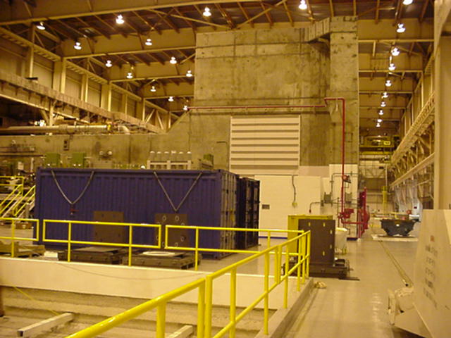
| This first picture is of the BioShield. It is a 6 foot thick wall of cement around the turbine and the valves. The purpose of the BioShield is protect people walking around on the turbine deck while the plant is operating. The Steam that flows through the turbine during operation is extremely hot (temperature) and gives off 2 gamma rays for every atom as part of the decay of the Oxygen to Nitrogen-17. When the plant is not operating it is very safe to walk inside the BioShield without recieving a measurable amount of dose. The entrances into the BioShield are offset so not to allow a direct line for the Gamma Rays to travel. I was trying to give you an idea how big this thing is but you just might have to take my word for it, it was big. |
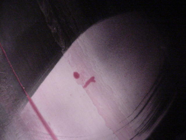
| One of the tasks the group wanted to accomplish was to investigate a "crack indication" (not a crack) on the Seat of the #1 - High Pressure Control Valve (of 4 total Control Valves). The indication was noted at an earlier outage and they are keeping track of its progress. To get this picture someone had to crawl through the pipe while the Control Valve was removed for cleaning and repairs. Since the Steam that goes through the pipe comes directly from the reactor (the difference between a BWR-Grand Gulf and a PWR) and there is fixed contamination in the pipe the pipe was a contamination area. This required the person taking the picture to dress out in order to take the picture of the crack indication. |
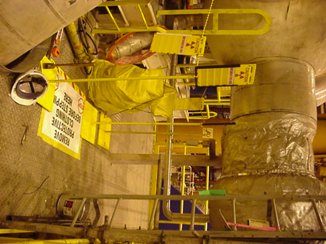
| This is a typical entrance to a Contaminated Zone on the Turbine Deck. Almost all of the contamination of the turbine deck is "fixed contamination" which means it does not fly around and makes it difficult, nearly impossible, to become contaminated unless you are cutting the material. Note the clear plastic trash bag next to the "Step off Pad" (the white square on the ground). This for used PCs when a person is done in the contaminated zone. |
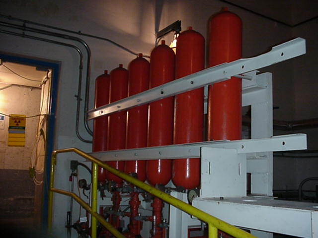
| These are EHC (Electric to Hydralic Controls) Accumulators. They store EHC fluid in case of emergancy. EHC is the system that operated the actuators that open and close the valves on the steam pipes. These bladders are kept stored with enough EHC fluid to close the valves in order to stop the steam cycle in case the normal system is not operating correctly (example: Lose of on-site electric power.) |

| This is the Electric Generator. It is connected to the turbines by a large shaft. When the turbine
is connected to the generator it is not the amount of steam flowing through the turbines that controls
how fast the shaft spins. It is the frquency of the electric current - 60 Hz. Which means the shaft
(and turbines) spin at 1800 rpm. Note: for the people who do the math, try having 4 poles instead of just
2. I actually got to climb on top of the generator during the outage (we had to wear harnesses because the top of the generator was higher than 6 feet. I was helping someone look for airleaks with a chemical called "Snoop" - very similar to soapy water. We found two leaks while we were up there. The generator has to be completed sealed up because it uses pure hydrogen as coolant, which you probably know, can cause problems and leaks mean a lose in power. Normal air is pumped into the generator after the plant comes offline and when we found leaks it was just normal air. |

| This is one of the contractors who came to the plant for the outage. He saw me taking pictures and asked if I would take a picture of him laying around to send to his wife. He was working on the seal oil system. Seal Oil is used on the bearings inside the generator. Again, becuase of the hydrogen coolant the generator must be completely sealed. |
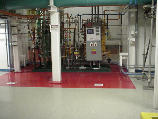
| The Generator is cooled by Hydrogen that is sealed into the generator. This is the controls to that hydrogen system, it is called the "Gas Rack". |
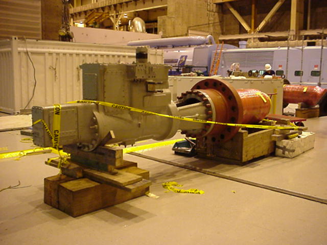
| Here is a picture of the High Pressure Control Valve (HPCV) and actuator. This is the actual valve that controls the flow of steam into the High Pressure Turbine. Note how the far end is covered in pink wrap and caution tape; this is becuase the valve is highly contaminated (fixed contamination). |

| This is some equipment we had on the HPSV to machine a special metal pin (why I don't know) but this picture was for my boss during the outage. |

| Another picture for the boss. |
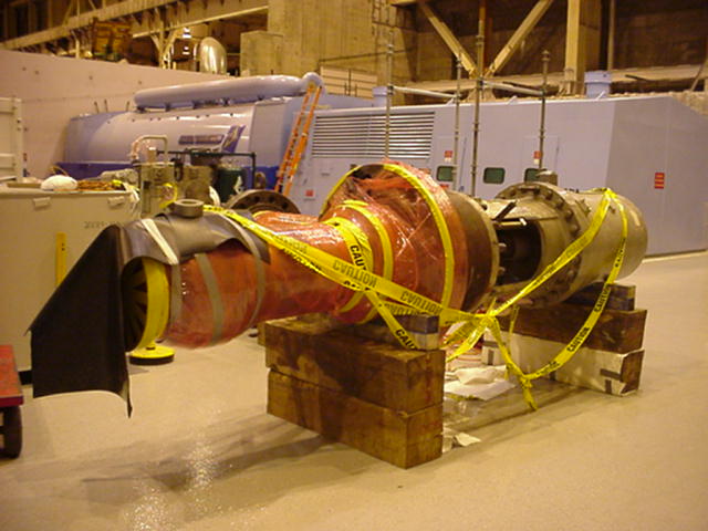
| This is the High Pressure Stop Valve (HPSV) and actuator. Note that one end if covered in pink wrap and caution tape. Again this is because the valve is highly contaminated. This is source of highest radiation dose rate while I was at GGNS RF-12, 2 millirem/hour. Which means (as it says) if I stood next to the HPSV for one hour I would recieve 2 millirem of dose, which is a relatively small amount. But of course I did not stand next to it for very long and did not recieve a measurable amount of dose during the entire Refueling Outage. |
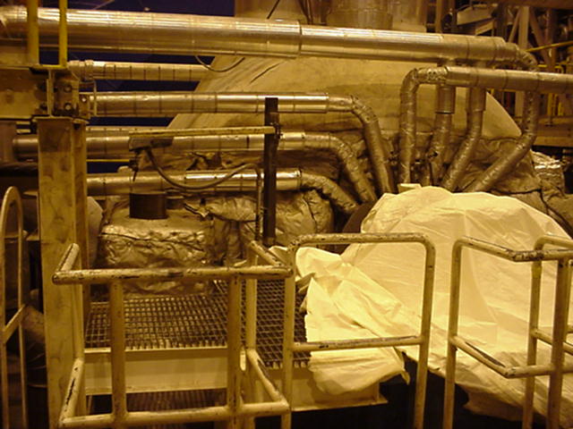
| There are 4 pipes, that each run through 1 HPSV and 1 HPCV, that flow into the High Pressure Turbine in parrallel which are at the
very top of the picture (you can bearly see them). The igloo looking thing is the insulation for the
High Pressure turbine (which is much smaller than the Low Pressure Turbines). The insulation is to keep
heat inside the system. The part that is covered by the white tarp is the "Over Speed Stub Shaft". It is attached to the main shaft which is actually 4 seperate pieces that are coupled together. The Over Speed Stub Shaft is set to trip the turbine offline if the turbines get spinning too fast (105%). |

| These large pipes, called the "IsoPhase Bus", are actually series of wire that carry the electricity out of the plant to the transformer then through the Breakers and then out to the Grid where people like you and me can use it. There are 3 buses for the 3 phases of the electricity (like a three phase motor, in reverse putting out power instead of taking in power). This picture was taken right below the generator. |
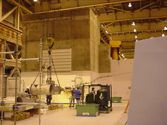
| Here are a series of pictures taken of the team moving the Low Pressure Control Valve back into place after repairs and maintenance were completed. It was the first lift using the big crane I had ever seen, so I was pretty impressed - hence all the pictures. |
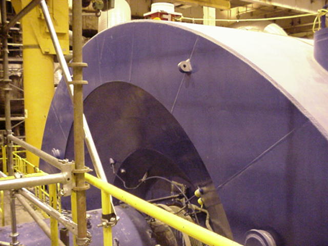
| Temp |
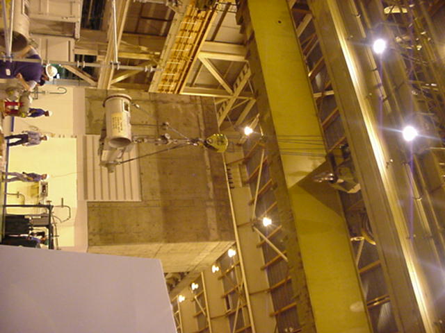
| First they picked up the LPCV straight up. |
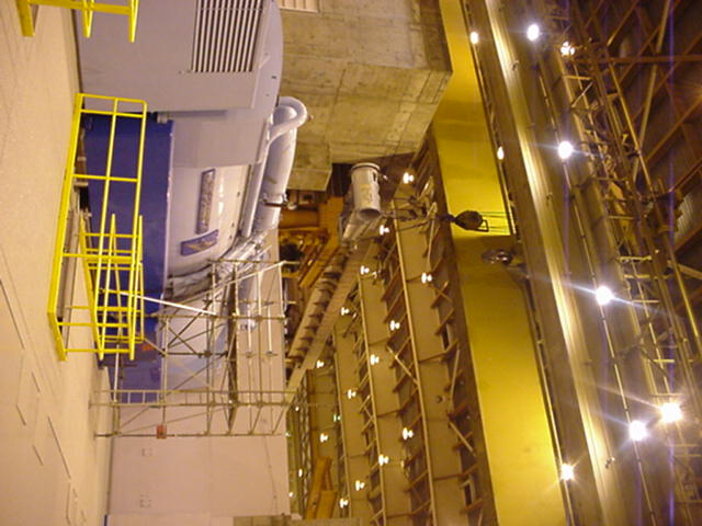
| Then they moved it out above the generator so they could get around the BioShield. |
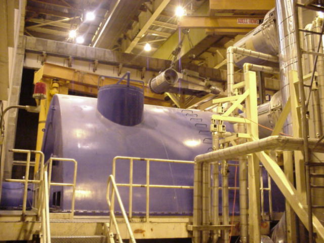
| As they went over the low part of the BioShield the LPCV was moved over the LP Turbines. |
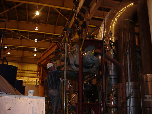
| This part took a while for them move the LPCV into position. They had to navigate several pipes and tubes that would later be hooked back into the LPCV. Another problem was that the man operating the crane could not see were the LPCV was because the BioShield was obstructing his view. So a person on the ground with a radio had to relay movement commands to the operator. |

| It was so tedious that I got bored and took another picture. |
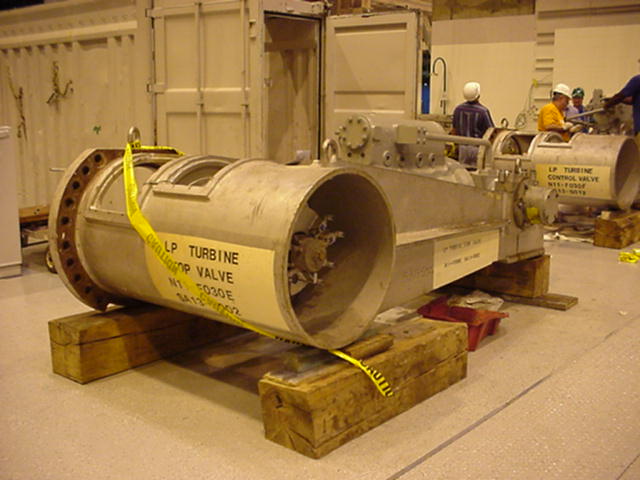
| This is a picture of one of the Low Pressure Stop Valve actuators. There are 2 LPCVs and 2 LPSVs for each LP Turbine (3) for a total of 6 LPCVs and 6 LPSVs. They were just doing routine maintenance and inspections on this actuator and the valve. An interesting point, this picture is on just the actuator, unlike the HPSV and HPCV which came out with valve and actuator combined. |
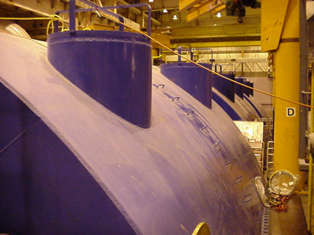
| Here is a picture of the 3 Low Pressure Turbines. It is kind of difficult to make them out but it was hard to get a good picture because they are so large and it was impossible to get at a good angle to take a picture. The vent looking things on top are relief valves. They are closed unless too much pressure builds inside one of the turbine cases (but that would be a bad thing). |
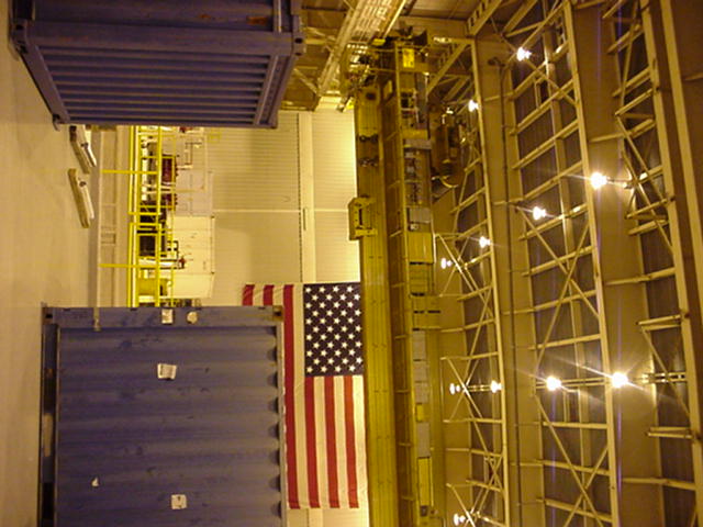
| Now this thing is big. The whole yellow section moves along the sides of the building. Then the lift section can tranverse across the entire length of the crane to reach anywhere on the turbine deck. One problem with the crane, which I talked about earlier with the setting of the LPCV, is that the operator is along the left edge of the crane and is not able to see past the BioShield. |
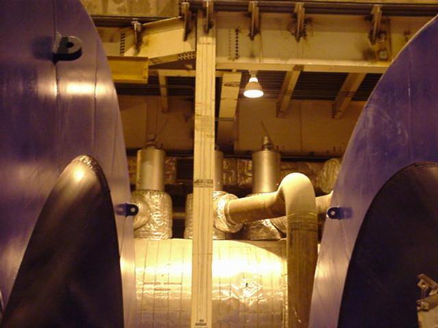
| This is a picture between two of the LP Turbines at the Moisture-Seperator-ReHeater (MSR) Relief Valves. Again these are usually closed except when something is going wrong. The turbine team had a tough time with these valves because some other group was working on them and required the main crane to do their work and could not work on the LPSV and LPCV which was below and to the right and left of MSR. |
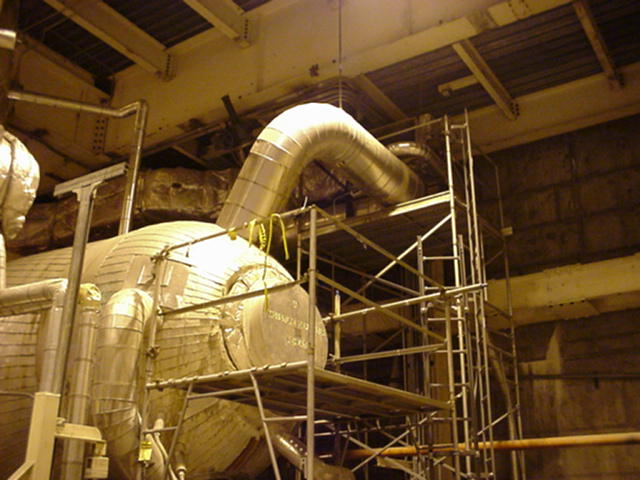
| This is just another picture of the MSR. The purpose of the MSR is take some steam out before it runs into the HP Turbine and put it directly into the LP Turbines (which run in parrallel) in order to optimize the use of the steam. 85% of the total power produced by the turbines comes solely from the HP turbine. |
.jpg)
| Some of the rigging the other group of workers was using to work on the MSR Relief Valves. I climbed some scaffolding (with a harness) to take this picture. |