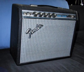
The Vibro Champ is the same as a Champ with added Tremolo.
The
tremolo is somewhat unique in that it results from
modulating the bias
of a pre-amp tube via it's cathode. Most tremolos
are output tube grid
bias or pre-amp signal modulation.
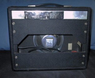
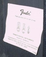
Below are some of the pics from the ebay ad.
Can you spot what's
"wrong" with the 2nd and 3rd pics?
Top cover is upside down.
Tube chart shows only 3 tubes
The seller said the tube chart was original after people
questioned it. It
wasn't a big deal to me since I know Fender was not
always careful about
tube charts. A Vibro Champ has 4 tubes because
of the added Tremolo.
The original speaker had a "rub" noise when playing
with any real
volume. All the reading I had done said to replace
the wimpy stock 8"
speaker anyway. Some change the baffle or cut
the original to fit a 10"
speaker. This would have sounded nice based on the
sound test I did thru a
'10 4 ohm Celestion speaker I have mounted in the
cab of a homebrew amp.

However, the vintage amp police would have issued a
warrant for me since
this would be a "destructive modification."
I went with a Weber 8a125-3.2. It's 8",
1.25" voice coiled, and 3.2 ohms.
I chose the ribbed cone and 15 watt options.
P8Q is the equivalent Jensen
model# and it's AlNiCo. Top of the line for
8" @ $80. The "Signature
Series" AlNiCo Weber is $45 and the ceramic model
is only $24.
The Weber site mentions that this "Vintage" replacement
speaker model
is "For late BF and all SF Champs with 8" speaker."
However, it would
have interfered with the stock main cap can if I had
not changed it to one
that happens to be shorter. I would have needed
to snip off or bend one of
those "tangs" on the speaker basket or re-position
the mounting studs
about 22 degrees to rotate the "tang" out of the way.
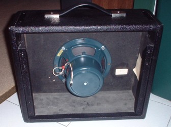
New Weber (much manlier)
The 8" Weber sounds almost as good as the 10" Celestion
and light-years
better than the stock speaker.
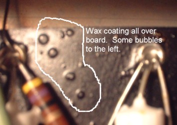
One of the 1st things I noticed when removing the chassis
was that the
component board and components were coated in wax.
Seems to be a
factory application but who knows. I guess it's
to prevent oxidation.
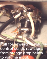
Having built the "Tweed" Champ homebrew I knew the
amp would be
capable of producing nice distortion if the tone circuit
was bypassed. A
Tweed era Champ has no tone control circuit (which
reduces gain.) To
achieve this mode as an option, I installed a "Pull
for Tweed" control. I
replaced the stock volume control with one containing
a switch. The
switch turns on an added cap that sends all the signal
from the 1st gain
stage directly to the volume control's input.
This bypasses the bass and
treble circuit ("tone stack") which reduces midrange
frequencies.
The switch works great. I do have to keep the
volume on zero when
engaging the "tweed" mode to avoid a single "pop"
noise from the cap
charging itself. Once it's charged, subsequent
switching won't cause
any pops during a session.
Click Here for comparision in sound.
Not a huge difference. More volume, grit and
sustain.
This model amp defaults to "on" as far as the Trem
effect. A pedal is
needed to switch it off. Without a pedal, one
must turn the control down
to turn it off. I use a pedal board that has
a switched rca jack on it.
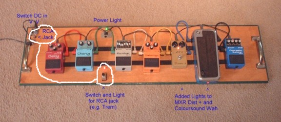
Problem was the light for the control switch comes
on when the switch
is "closed." The stock wiring for this amp turns
the trem "off" when
it's jack is "closed." I needed the trem to
come "on" when the switch
is closed so I could continue to use the pedal board
as is with all my amps.
I had made this default change to another amp based
on a schematic
I have for the Gibson Hawk. Instead of grounding
"off" the trem's
oscillation circuit, I re-wired amp's the rca jack
to ground "on" the
ground connection of it's speed control leg.
Breaking this stock
connection turns the trem off thus changing the default.
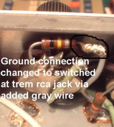
Worked fine.
The only "failed" upgrade also involved the trem.
I had read people
complaining that turning the "intensity" control
up would reduce the
overall gain/volume of the amp. Even with the
default now set to "off"
I did notice this phenomenon while turning the "intensity"
up from "0."
Looking at the schematic I could see that this control
sends DC out along
with the needed ac that creates the "pulsing" trem
effect. Problem is
that this DC "leakage" from the control changes the
base idle of the tube
the control modulates with ac. The more you
turn the intensity (of the
effect) up, the more DC that comes out too causing
overall volume/gain
reduction. I wanted to be able to leave the
intensity control "up" (even
when switched off) but avoid this gain reduction.
My idea was to block
the DC from getting out with a cap since that's what
caps do. Problem
was choosing and finding an appropriate value.
The (good) ac output can
be pretty "slow" in terms of "frequency" requiring
a very large value
cap. Set on the slowest setting, the ac output
is probably about 3-5hertz
(pulses per second.) The higher the value of
a cap, the lower the bottom
range of the frequency that can get thru. This
means I would need a
very high value cap to let the very low frequency
ac thru. I also needed
to consider what DC voltage would end up on the cap
and use a rating
high enough. I did a test with a 250u/25v cap.
The DC on it would move
up to about 22v which was "ok" but the trem effect
was not as strong as
it should be. Not enough of the low frequency
pulse was getting thru the
cap. I then tried a 2200u/35v cap.
It was better but still the effect was
not strong enough. Both caps did eliminate the
"gain reduction"
phenomenon but the loss in the trem intensity was
too significant to leave
the mod in. A cap with a high enough value would
probably be huge and
expensive so it's back to stock now.
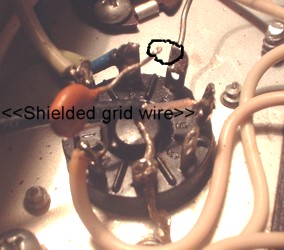
I noticed there was a cap on the 6v6 output tubes socket.
I was familiar
with the grid-to-ground caps on the larger SF Fenders
but had not seen
this grid-to-cathode cap before. I also noticed
that it was not used on the
earlier BF era Champ models just like with the larger
models. The
purpose of this cap is to prevent unwanted oscillation.
The sloppy wiring
job of the new SF era was causing oscillation and
this was the Band-Aid
fix. Problem is that it robs some tone by reducing
higher frequencies. I
had snipped them off my '71 SFDR amp with no oscillation
resulting so
I tried it here. After this snip, playing low
or loud notes caused a
buzzing noise. ;(
It did sound clearer so I wanted to fix the oscillation
while leaving the
cap snipped. I tried moving the 6v6 grid wire
but that didn't work. I
then tried replacing the grid wire with a shielded
one and that worked.
The shield is grounded on only one end and prevents
those nasties from
getting to the grid wire itself.
I left the cap connected to only the cathode taking it out of the circuit.
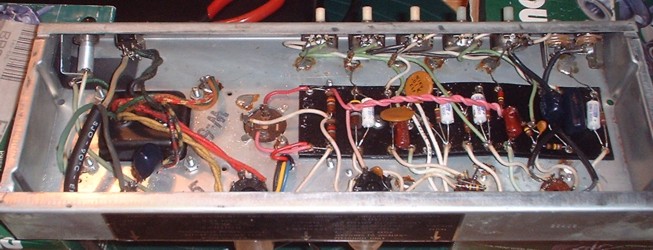
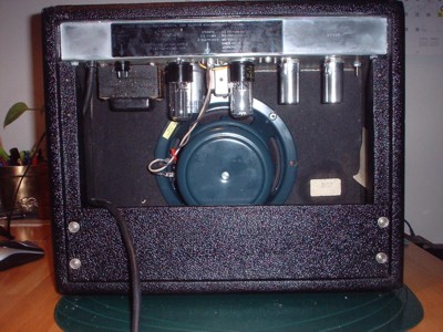
Below are "before and after" pics of the chassis.
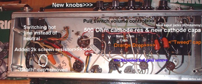
I changed all the electrolytic caps as part of a standard
10-15 year
tune-up. I upgraded the 6v6's cathode bypass
cap to 50v from the
stock 25v. The schematic itself (AB764) shows
24 volts DC on this cap
so a rating of 25v is not safe enough.
The schematic also shows the fuse and the switch on
the "hot" leg of
the line input but the amp had the switch controlling
the "neutral"
leg. Easier to wire but not the safer way. I
re-wired it the safer way.
I removed the "death" cap. I actually used it
to add the "Pull for
Tweed" option to my '71 Deluxe reverb since it's value
was
appropriate @ .047u. Worked nicely there too.
I added a 2k screen resistor to the 6v6. This
brought the screen voltage
down to 1v below the plate voltage which is "better"
than having this
screen voltage higher than the plate as it was running.
I thought it might
also make the 6v6 run "cooler" but it didn't.
To get the 6v6 down from
the 18+ watts it was idling at, I changed the cathode
resistor from the
stock (449 ohms) to 516 ohms. This reduced the
6v6's idle down to 16.8
watts. Still hot compared to the "book max"
of 14 watts (for class A)
but better than the implied schematic value of 18.8
watts. Maybe I'll
try a 740 ohm some day.
The #1 input jack went bad after about 2 weeks.
It was not shorting
to ground when not in use so hum was coming thru.
I tried re-tensioning
since it was weak but that went bad. I installed
2 new inputs since it's
easier than changing just one. I didn't bother
to wire up the #2 jack.
I changed 2 of the trem circuit caps only because the
modern ones are
smaller and thus don't need to be bent and look neater.
Only cost a few
pennies too.
This model uses the chassis for one side of the heater
circuit. Many say
that this is more likely to cause hum since it presents
6.3 volts to ground
inside the tubes instead of 3.15 volts. I intended
to change the heater
wiring to "balanced" with an "artificial center tap"
to reduce this hum.
Problem was, there is no hum even when maxed.
I left it alone.
There's almost no hiss either so I didn't bother to
change the plate
resistors.
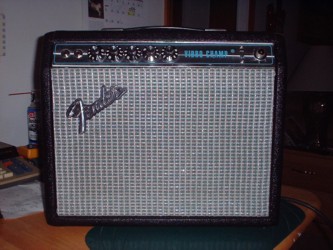
Final pics:
All the tubes were original RCA's. I put in a
new 5y3 rectifier tube only
since I have extras. One new one was bad as
seen by the mini lighting
display I saw between it's plates. I put away
the 6v6 power tube for
posterity. It tested weak on my circa 1945 Precision
brand tube tester.
I replaced it with an NOS RCA silver plate 6v6.
I moved the stronger
12ax7 tube to the trem position and put away the weaker
one. I use
either a used Mullard short plate 12ax7 or Ruby 7025
or EH brand
in the pre-amp slot.
It's a great amp for practice or for use with a mic.
It wouldn't be
loud enough on it's own for jamming. This lets
you crank it up for nice
distortion w/o disturbing the neighborhood.
And the "Pull for Tweed"
kicks it from crunch to gain city. A fun new
toy.