Well, I have heard great things about the MSD, and I figured I might as well get one with a rev limiter too. A few of the benefits of a ignition system are: easier starting, multiple spark discharge, more powerful spark - hence, a better combustion in the cylinder across the entire RPM range. The first step was to find a MSD 6AL ignition system and MSD Blaster coil. I found the MSD 6AL from a list member in FL, and ordered the coil new from Summit. I also purchased a MSD wiring harness (Part# 8876) in order to maintain the clean, professional appearance and to make the installation a tad easier on myself. Additional items that need to be purchased for this installation are #10 guage electrical wiring. 3/8" protective wire hosing (corrogated black hosing) is optional. Step 1: Remove the air cleaner and pull all the stuff out of the way. Disconnect the factory harness from the OEM coil. Using a 10mm wrench, remove the two bolts holding the OEM coil to the manifold. Once you have the coil removed from the engine you will need to separate the coil from the "bracket" that holds it to the manifold. You need to use this bracket for installation of your new coil. This can be accomplished by drilling out the 2 rivets at the bottom of the bracket that hold the two pieces together (my SS only had screws, no rivets. Maybe they were removed by a previous owner.) After separating the OEM coil from the bracket, place the MSD Blaster coil in its place. There is a 2 bolt/nut combo in the MSD coil kit that will replace the original riveting on the bracket. Re-assemble the "bracket" with the new Blaster coil and bolt it back onto the manifold. To test the new coil, connect the OEM wiring harness back up to the new Blaster coil and make sure that the engine starts. If it starts, your coil is good and you can keep going. Step 2: Choose a location for the placement of the MSD ignition box. You want to keep it away from high heat sources and have it installed securely to metal. I chose a mounting location on the driver-side, in front of the tire well. I had an aluminum cover made in an attempt to camoflauge it. If you look at the pics at the bottom of the page, you can see the box is hid by the charcoal canister and purge valve, but still gets fresh air and the chips are easily changed. Most other people mount it to the fender, pretty much directly above where mine is. If I paint the aluminum box, it would be pretty stock appearing. The only thing that I ran into a problem with is the mounting tabs for the aluminum box were small, and I had a hard time trying to locate mounting screws through the box and the thick rubber inner fender. The only drawback to this location is the long distance to route the ignition positive cable to your battery, but this is a minor inconvenience. Mark the 4 holes from the ignition box onto the mounting location. Next, drill a pilot holes into the markings. Using the screws (that are supplied) and the locking washers, mount the ignition box securely on the car. Step 3: Connect the Dual Connecter Harness (Part# 8876) to the ignition coil (use the 2 prong connector and hook it to the driver side of the coil). Next connect the factory harness (the one that you unplugged from the OEM coil) with the 4 prong connector of the Dual Connecting Harness. Both connections can only go on one way so it makes it tough to screw it up. The Dual Harness is connected to the Factory Harness (4 Prong) and placed above and behind the distributor cap or zip tie it out of the way. The Dual Harness (2 prong end) is connected to the Blaster Coil on the DRIVER SIDE. The remaining 4 colored wires on the Wiring Harness match up with the red, white, orange, and black connectors from the ignition system. Using the routing hose, run the connectors from the ignition system around the back and top of the engine bay to the distributor cap. You can route the hose through a loop ring on the power brake booster which will help keep it in place. The routing hose will provide additional protection to the system wiring and keep it neat and orderly. Connect the 4 color coded male/female connectors from the Wiring Harness to the Ignition Box wires and make sure they are secure. Step 4: The last step is to connect the ground and the positive cable for the ignition system. If the ignition system is mounted on the driver-side, the negative cable can be grounded on the frame in several locations. I chose a part of the fender right above the vacuum canister. Be sure to clear away all paint so that a good ground can be established with the metal. Next, attach the #10 guage wire to the Ignition Box positive cable with a wire connector (make a good connection) and route this wire around to the battery. Using a post connector, I attached the positive cable to the battery. Again, take the additional time to ensure that you have a good secure connection to the positive terminal of the battery. Step 5: Go ahead and fire the car up before you replace the air cleaner assembly. Make sure that everything is in working order before you replace the assembly. If the car turns over but does not crank you probably have a loose connection. Go through your steps and double check all connections beginning with the Blaster Coil - Dual Harness connection. The ground and power wires are very important to this system!! Additional Notes: Total installation time was approximately 2 hours . I would strongly suggest replacing the distributor cap/rotor, spark plug wires, and spark plugs if they are approaching the replacement point. Remember to upgrade your spark plug wires to a spiral wound set that are at least 8mm. Personal Information: If you want to save yourself $15, you can go without the Wiring Harness. However, I can tell you that the time and ease of installation with the Wiring Harness is well worth the $15 not to mention if for some reason you need to bypass the ignition system you can revert back to the OEM wiring with a couple of unplugs. |
| On November 13, 2000, I installed new Taylor wires (#74602). A note on the wires, they are not the application for a stock 87 SS w/ L69. That part number is for blue wires on a 87-95 Chevy truck with a remote coil. The reason is because I installed the headers already and the Monte wires had a 180* plug on the #8 cylinder which would have burned. So instead of making my own from a universal set, I ordered this custom set. They fit great except the coil wire is a little long, but no big deal. I reused these when I did the MSD 6AL and coil upgrade as well. |
 |
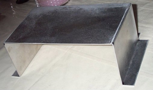 |
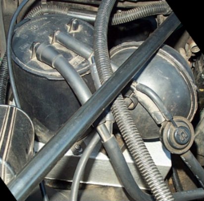
| Here you can see the aluminum box I had fabbed up. I need to go measure it again, but it is a VERY close fit. The top of the charcoal canister comes close to resting on the hood. In the future I plan to relocate the vacuum ball underneath the inner fender, and the charcoal canister to an aluminum plate mounted behind the headlight. As long as you have someone that can do some metal work, the installation was just drilling holes and putting some bolts and nuts in, easy as pie. With this setup the MSD is pretty much hidden, but I can still reach the front of the unit to change RPM chips, and it still gets plenty of fresh air. |