Another TCS pair is back on the air!
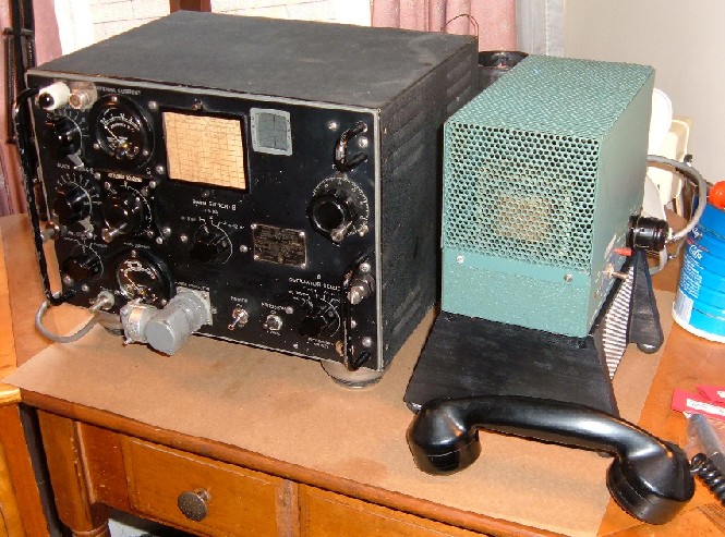
Shown above is my COL-52245 TCS-12 transmitter.
Also shown is a modified Heathkit HP-23A for powering the rig.
It took me 10 years to get around to repairing this transmitter. I bought it from a retired electrician in the mid 1990s. He was cleaning out his basement. At the time, I was interested in the boxes of vintage parts and tubes and other vintage radios, including a 1938 Zenith shutterdial console and a Hallicrafters S-85 general coverage receiver, that were part of the deal. For a couple of years, I used the transmitter as wintertime ballast in the rear of my Chevy S-10 Blazer. It weighs 50 lb. and those beefy handles on the front panel make it relatively easy to lift.
All the knobs and meters were present in the front panel, and there were minor chips in the panel’s black paint. The power switch was the only visible missing part. A round, 4-pin tube socket occupied the square power socket opening. Someone had relocated the original power socket from front of the rig to the rear, cutting somewhat irregular holes in the chassis and the louvered sheet metal cabinet. Inside, there were wires hanging and a gaping hole in the chassis next to two tube sockets. Every time I reorganized my basement, I would spin the knobs, stare at the rig, and wonder whether I should keep it.
I re-licensed in 2001, and upgraded to General and Extra. First licensed as a Novice in 1976 as WD8LGC, I let the ticket lapse due to time constraints.
I purchased a TCS-12 manual (a partial reproduction) from Fair Radio Sales in late 2002. I started repairing the transmitter and then set it aside, because it needed so much work. There were many loose wires, and I didn’t have a suitable power supply. Then in March 2005 I mentioned the rig in an email to a ham buddy in Colorado. He goaded me into hoisting it up on a desktop for another crack at it. He also suggested modifying a Heathkit HP-23 to power it. I searched on the internet and came up with an article describing how that can be done. The article, in .PDF format, is here:
http://www.vmarsmanuals.co.uk/newsletter_articles/newsletter_technical_articles.htm
Search for G3XSJ on the above web page, in the "Issue 35 - June 2004" index of articles.
A parts list was not included in the partial manual I purchased, so I downloaded a complete TCS-14 manual in .PDF format from The Wireless-Set-No19 website:
http://www.royalsignals.org.uk/
Free TCS-13 and TCS-14 manuals are at the website above, near the bottom of the page. The files are quite large- 24 MB or so. An email must be sent requesting a password (also free) to view the manuals.
The TCS-14 transmitter is very similar to my TCS-12 unit. Fortunately, the parts list in the TCS-14 manual included a brief description of the parts. This was very helpful, because quite a few components were missing inside my rig.
I did not have a suitable power plug for the power socket. I thought they might be expensive or unavailable. It took some time, but I was able to locate and purchase a right angle Cannon plug from the Wm. Perry Co. in nearby Louisville, KY. Once I had a mil. std. power plug, I relocated the power socket back to the front panel. Then I patched the irregular holes at the rear of the rig with sheet aluminum. The patch doesn't look bad, and it's at the rear anyway.
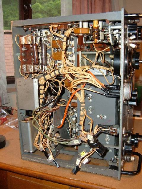
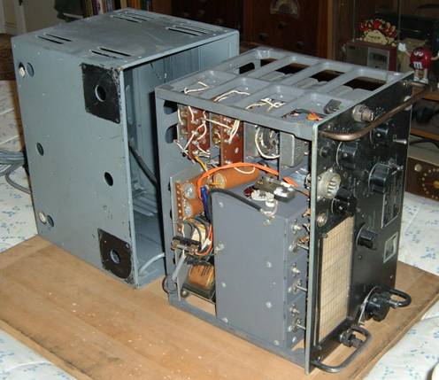
A fair number of loose wires- but it could have been worse.
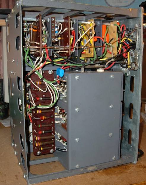
I identified all the missing parts, several that didn't look so good (blistered resistors, etc.), and a few resistors that had gone out of tolerance with age. I also decided to replace all the big oil-filled capacitors- probably full of PCBs anyhow.
Most of the components connecting the microphone jack to the grids of the push-pull 1625 modulator tubes had been removed, leaving loose solder-tinned leads. The part that concerned me the most was the missing mike transformer- 75 ohm primary, 125,000 ohm C.T. secondary. I looked high and low on the web. The closest I found was a similar one at Fair Radio Sales, but it didn't have the C.T. secondary I needed for the push-pull modulator. So then, I started considering mods to the modulator, and came across a discussion on the internet where someone told someone else about how "old timers" would reverse an old doorbell transformer to match a carbon mike to a modulator. Hmmm. Sounded interesting, but didn't solve the C.T. problem at all. But then a flash bulb (remember those?) went off. Small power transformers are readily available which produce 5V output from 115 VAC. And many of them have dual primary windings for 115/230 operation. Wiring for 230 VAC produces a center tap! The turns ratio is then 46:1, which will reflect a 75 ohm carbon mike load at the 5V winding as a 159,000 ohm load (square of the turns ratio) at the 230V winding. Close enough. So I ordered the smallest available (1 watt) Tamura power transformer from Mouser.com, along with most of the resistors and capacitors I needed.
I opened and inspected the "exciter" May 10, 2005, 60 years to the day after it was tested. The inside (about 1/2" ID) of one of the white ceramic coil forms was stained brown. Closer examination of the form revealed several... legs!!?? Inside another was a small long-legged spider, the type commonly found inhabiting cellars here in the Midwest. I poked and prodded until I evicted the mummified invaders. The other intruder was a cockroach, as best I can tell from the remains. Both had apparently crawled into the exciter loooong ago.
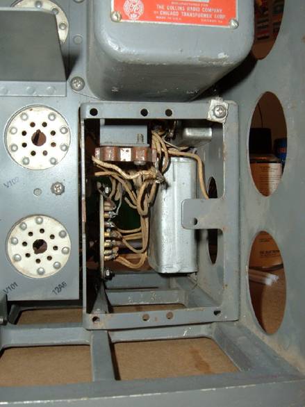
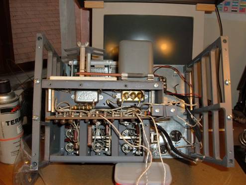
Someone hacked out the crystal sockets.
I am quite certain someone started to modify this transmitter 30 or 40 years ago. I believe they were going to add an amplification stage to the modulator to allow the use of a more modern microphone. They also removed the crystal sockets and most of the components in the crystal oscillator circuit. One of the hardest things to do was figure out where the loose wires ended up. Most of them disappeared into a wiring harness. The color coding on the wires was virtually useless because it had faded with age. I installed new oscillator components and fabricated a plate to hold (2) HC-6/U and (2) HC-17/U (FT-243) crystal sockets. I also reversed all the modulator mods using new components, so the rig still uses a single button carbon mike.
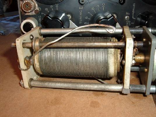
Roller inductor on the bench- to be cleaned and lubed.
The silver plated wafer switches and tube sockets were heavily tarnished, so I went at the rig with "tuner cleaner", Deoxit, and pipe cleaners. I used heavy bond paper soaked with Deoxit on the relay contacts. The antenna loading inductor was grungy. The inductor got a mineral spirits bath, a Deoxit workout, and a lube job.
I was able to purchase a Heath HP-23 power supply on eBay for conversion to power the TCS-12. Well, actually, I purchased two of them. The first came with a Heath HW-32 20 meter transceiver for $103, purchased from a ham in Connecticut. I originally intended to sell the HW-32. Two problems. One, both the HP-23 and the HW-32 were in very good condition. Two, I never saw a radio I didn't like. So, it was back to eBay to set up another search. HP-23s are auctioned quite often. In no time, I purchased an HP-23A for $36 from a ham in Texas. It had some minor surface rust, mainly on the transformer laminations. It powered up the HW-32 quite nicely. So, this one was perfect for the TCS-12.
I converted the HP-23A's 800 VDC voltage doubler to a 400 VDC full wave rectifier. I added a series resistor to the 250 VDC output to give 210 VDC under TCS-12 load. I also found the 12 VAC filament supply output to be a bit on the high side (13.8 VAC), so I added a 1 ohm series resistor to drop this to 12-12.6 VAC under load.
The (3) 12 volt relays (for T/R switching and for switching CW vs. voice circuitry) in the transmitter were a concern. The HP-23A has 12 VAC output, but not 12 VDC. I ended up purchasing a fully regulated Tamura 12 VDC 1 amp linear power supply chassis for $10 from a local surplus electronics store (Debco Electronics) to power the relays. I considered using a wall wart for this, but the relays can consume as much as 700 mA and as little as no current at all, so I was concerned about voltage regulation. The regulated power supply and a 12 VDC fan were built into an add-on wooden enclosure, which I attached to the bottom of the HP-23A (see the photo above).
Next, I removed the original connector from the end of the HP-23A's power cable and replaced it with the Cannon power connector.
The tube complement appears to be original, down to the Navy anchors stamped on the tube bases. I tested the (3) 12A6s with my old Hickock tube tester. One tested a bit weak, but so far I have not replaced it. I was not able to come across a tube tester which could handle the (4) 1625s. All I could do is check the filaments for continuity and check for direct interelectrode shorts with a multimeter.
Anyhow, I lit the firebottles July 7, 2005. It worked! Both CW and AM, with both the VFO and crystal oscillators. While testing the rig with a dummy load, I switched the positions of the (2) 1625 modulator tubes and the (2) 1625 final amp tubes to determine whether there were poor performers in the group. No doubt, the Collins engineers had this sort of troubleshooting in mind when designing the set. The tubes seemed to function equally well.
I have been on the air with a vintage telco handset (shown in the top photo) with a carbon element. It’s probably the same vintage as the TCS-12! It seems to modulate fairly well. I also purchased a New Old Stock (NOS) Shure 102E carbon mike on eBay, which doesn’t seem to modulate the rig quite as well as the handset.
Someone replaced the antenna binding post with an SO-259 connector. It seems more difficult to achieve a proper match with the antenna and there is a considerable amount of hum in the carrier at certain frequencies using coax. At some point, I’m going to reverse the SO-259 back to a binding post. For now, I just connect a single insulated feed wire to the center socket of the SO-259, and a wire from the ground binding post to the station ground.
I've found that the transmitter loads a random wire quite well. My understanding is that the transmitter is designed to load a vertical whip. This makes sense, since it was deployed on ships and military vehicles with a lot of steel to use as a GND.
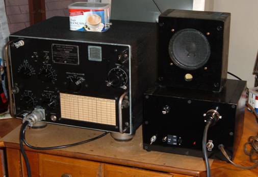
Shown above is my CIH-46159-A TCS-13 receiver.
Also these homebrew items: power supply, power cable,
speaker enclosure, and audio matching transformer.
My most recent acquisition is a TCS-13 receiver. Like the transmitter, it had been substantially modified. Both the BFO and audio power amp stages were hacked up, and an internal power supply was added. An SO-259 antenna socket was installed at the rear of the cabinet and the holes in the front panel for the antenna and ground connectors had been plugged. Very little of the original wiring harness remained. The oscillator selector wafer switch was missing, but fortunately the crystal sockets were intact. I set about reversing the mods, with the intention of restoring the set to its original functional condition using a combination of new and old stock components, with power and audio going through the original power connector on the front panel.
TCS-13 receiver- upon arrival at my QTH.
A rather straightforward (but tedious) process of identifying and removing mods ensued, followed by a fair amount of rebuilding. While I was at it, I replaced out-of-tolerance resistors and all of the oil-foil-paper capacitors.
Final stage of receiver “de-modification”.
I acquired a second receiver, a TCS-12 model, at virtually the same time as the TCS-13. This unit was damaged in shipment by the shipping service with brown trucks. It was double-boxed, but they somehow managed to put a half-inch deep dent in the front panel and a matching dent in the cabinet. Most of the tubes were rattling around inside the rig when it arrived. Needless to say, I filed a claim. Brown’s insurer ended up reimbursing me in full. So the TCS-12 receiver ended up as a parts donor rig. I pulled the antenna and ground connectors and the oscillator selector wafer switch for use on the TCS-13.
After the receiver rebuild.
I scavenged as many parts as possible from the internal power supply that someone added for use in my homebrew external receiver power supply. I ended up using the 12VAC filament transformer and a 1:1 (117VAC) isolation transformer, which had been used for B+. Not satisfied with the resultant 170VDC, I ordered a 28VAC transformer from Mouser.com and wired its primary in series with the isolation unit, producing a more nominal 210VDC B+ under load with a full wave bridge. Duncan Munro’s PSU Designer II power supply freeware was very helpful. I had a 1.5HY, 200ma, 90 ohm choke in my junk box. Using the choke in a 200uF/1.5HY/200uF pi filter resulted in very low (less than .1V) B+ ripple. Of course, with so much capacitance, it is necessary to avoid rectifier and choke damage from initial current surge, but PSU Designer II gives you a handle on this. PSU Designer II is available at:
http://www.duncanamps.com/psud2/index.html
The transmitter has a relay which cuts receiver screen voltage during transmit. Since I’m using two independent power supplies for the transmitter and receiver, it was necessary to replace this function. This was accomplished with a two-transistor T/R switch built into the receiver power supply. The switch senses the voltage present at the “Key” pin on the transmitter power connector- 0VDC during transmit and 12VDC during receive. The transistor output drives a small Omron relay from Mouser.com to provide +210VDC to the receiver screens.
The homebrew power cable contains eight 18 GA. stranded wires. The outer jacket consists of two 4 ft. lengths of heat shrink tubing. The receiver end has a suitable Cannon power plug from the Wm. Perry Co. At the power supply end there’s an 11-pin “octal” plug.
I put a matching transformer in a Café Francais tin with two RCA jacks. Well, actually, the transformer is a 12VAC wall wart that was collecting dust. The 10:1 turns ratio seems to provide a good impedance match for my 8 ohm 5W speaker. Before you come down to hard on me for using the wall wart, consider that the power amplifier output transformer in the receiver is only rated 200-5000 Hz. As for the tin- what the heck- it’s always hidden behind the receiver.
I stripped the cabinet and re-sprayed it with Krylon black Wrinkle Finish paint, which I found in spray cans at my local Pep Boys auto parts store. There’s a fine line between applying too little vs. too much paint on vertical surfaces. Coats that are too thin dry gloss black. Thick coats can run. Krylon recommends 2-3 heavy coats at least 5 min apart. If the wrinkle finish is unsatisfactory, it is possible to re-coat after 2 hours. If you ever try this paint, I recommend practicing on a small vertical surface first. As for coverage- one can is not quite enough for a TCS cabinet. After chemically stripping a cabinet, the inside will need repainting to prevent rust. It’s virtually impossible to keep the stripper off the inside surfaces. Keep a brass bristle brush handy. The original paint on the louvers tends to be stubborn. And I ended up using the old trick of covering the applied semi-paste, water clean-up stripper with aluminum foil for a few hours to keep the volatile stripper components from evaporating.
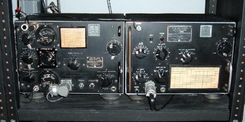
The TCS TX and RX in the shack.
If you want to try for a 160m, 80m or 40m QSO on the rig, drop me a line at jfahrenh<at>yahoo.com. Bear in mind, though, that AM output is only 20-25 watts!
Joe F. KC8RKL Webpage updated 21SEP2006
Click here to go back to my home page