Here’s a tutorial for working with NURBS to create a head. It covers using the trim tool to create eye
holes and then using a blend to attach the eye.
IMPORTANT NOTE: Before you do ANY of this, take a picture of
your character toy from the SIDE and the FRONT. Import those images into the corresponding views. The only reason I didn’t do that here is
that I didn’t have immediate access to a digital camera and I wanted to put
this page up quickly for y’all!
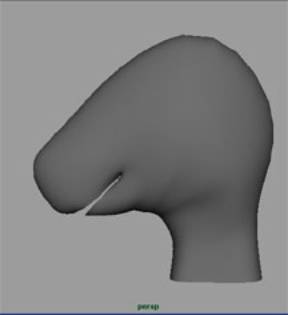
- Create a NURBS sphere and model it in the general shape of your
character toy’s head.

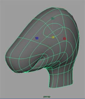
- Draw curves that radiate from the mouth (wherever that is on your
toy). Be sure to take the neck
into consideration.
- Split your head model in half and delete the half not seen in the
Side view. How: Select the two
isoparms on the half of your model (or create them if they’re not already
there). Then, select Edit NURBS > Detach Curves. Keep one half and delete the other.
- Select your curves and project them on your model. How: Edit NURBS
> Project Curves On Surface.
- Select the projected curves and duplicate them. How: Edit
Curves > Duplicate Surface Curves.
- At this point, you can either delete everything but the new curves
or Hide Unselected Objects. Delete
History on the new curves.
- Rebuild the curves so that they all have the same (manageable)
number of CVs. How: Edit Curves > Rebuild Curves and select the
little box. Click “0 to 1” for
Parameter Range and enter a number (probably not more than 10) for Number
Of Spans.
- Loft the curves together.
How: Select each curve in order one by one. Select Surfaces
> Loft.
- Delete History on your lofted surface. Group the curves (name the group “head_curves”) and hide
them or put them into another layer.
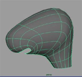
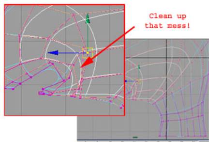
- Clean up the model. Look
for overlapping CV’s and spread them out.
Turn on hulls and smooth out the ones that look too jagged.
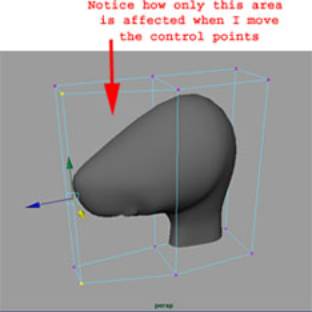
- Now you can start to tweak the model to get a better shape. In the case of my model, the nuzzle or
snout is much thinner than the rest of the head. So, I’m going to use a lattice
to achieve this. How: Select Deform > Create Lattice and select the little
box. Enter the number of Divisions
you need for X, Y, and Z. In my
case, I’m using 2 for X and Y, and 3 for Z (since the snout seems to
narrow dramatically starting from the middle of the head. Also I don’t want the neck to be
affected).
- Go into Component Mode by pressing F8 and then Move, Scale, or
Rotate the control points necessary to mold the shape you want. (To reposition the lattice without
affecting your model, select both the lattice and the base in the
Outliner) After you’re done, select your model and Delete History. This will get rid of the lattice. Note:
If you delete the lattice itself, your model will go back to its original
shape. Another
note: You don’t have to use the lattice!
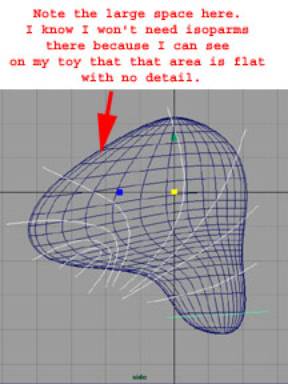
- Continue adjusting the model.
You may need to add isoparms or lattice another area. Note:
Add isoparms sparingly! Too many
will cause problems for you later on… moreso than when working in
polygons. Another
note: You can put a lattice a group of CVs and it will only affect
those CVs. Yet another note: I could’ve spent more time developing this
model, but I wanted to finish this tutorial for the class. Please don’t
use my model as a quality gauge for yours!!!
ADDING PARTS - EYES, EARS AND NOSE
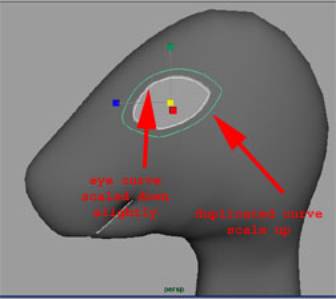
- Draw a curve in the shape of your toy’s eye in the Side view right
over the model’s eye area and then scale it up slightly. Now, project the curve onto the model.
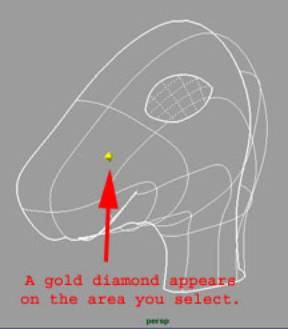
- Next, create the eye hole.
Select Edit NURBS > Trim Tool. Select the area you wish to keep (the
head) and press Enter. Now there
should be an eye hole.
- To build the eye itself, use the existing eye curve. Hold down the right mouse button over
your model and select Trim Edge.
Then click on the eye curve.
Duplicate that curve (Edit Curves >
Duplicate Surface Curves).
- Center the pivot of the curve (Modify >
Center Pivot) and scale it down slightly, so that it’s the exact
size of your model’s eye (remember we scaled the projected eye curve up
slightly). Duplicate it and move
the duplicate (in X, most likely) so that there’s a little distance
between the curve and the head.
This will become the eyelid.
Note: if the edge of the eye hole
looks jagged, select the model and press 3 for higher resolution. That should smooth out the edge.
- Duplicate that curve and scale it up so that it overlaps the
head. This will be the edge used
in the blend.
- Select the three curves in order.
Select Surfaces > Loft and the little box. Adjust the lofted surface so that the
edges lay flat again the surface of the head.
- Now you can Delete History on the loft and delete or hide the
curves. You can also add more
isoparms where there are gaps.
This will be beneficial when you apply the blend. You can also create an eyeball now and
fit your eyelids to it.
- Select the outer curve of the loft by holding down the right mouse
button over the curve and selecting Isoparms. Duplicate the curve and scale it up. This will be the outer curve of the
blend.
- Project that curve onto the head surface.
- Now is a good time to turn on the CVs of your loft so that you will
be able to see them even when the loft isn’t selected. Select the loft and then select Display > NURBS Components > CVs. ALSO, make sure that your loft is
closed and if it’s not, use Edit NURBS >
Open/Close Surfaces to close it!
- Rebuild that curve so that it has the same number of CVs as the
loft curves. Reposition the
projection curve CVs so that they line up with the loft curve CVs. Make sure that the U and the box next
to the U is lined up with those on the loft as well. This will ensure that both have the
same surface direction. If they
don’t, you’ll get a twisting effect when you apply the blend. Note: If the U is on the inner curve of
the loft (the one farthest away from the projection curve), reverse the V
surface direction (Edit NURBS > Reverse Surface
Direction and select the little box. Click V)

- Next, apply a Fillet Blend.
Deselect all objects, then Select Edit NURBS
> Surface Fillet > Fillet Blend Tool. Follow directions from there.
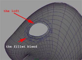
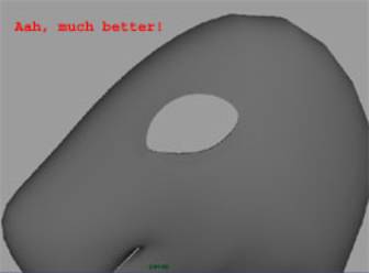
- After the blend is applied, you’ll need to smooth the transition
between it and the loft, especially if there is interpenetration of the
two surfaces. Do this by moving
the CVs on the outer curve of the loft.
by Jenga Mwendo; July 1, 2002 for 3D Modeling Class
at NYU