
The original concept for designing the hovercraft was to use an inexpensive, easily obtained lawnmower engine, or engines, and be able to support one adult, travelling over any reasonably smooth solid surface, grass or water.
The construction was to be simple, and easily within the capabilities of the average handyman, using materials easily obtained at any local hardware store. This ruled out exotic materials such as glass reinforced epoxy materials, leaving timber and ply as the preferred materials.
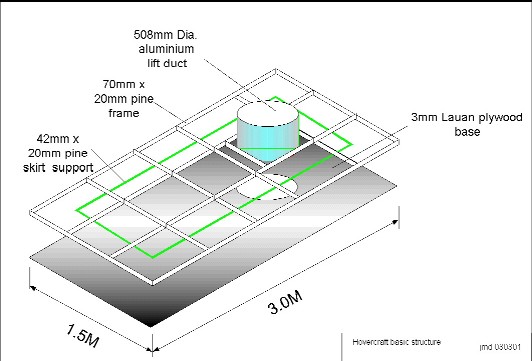
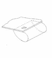
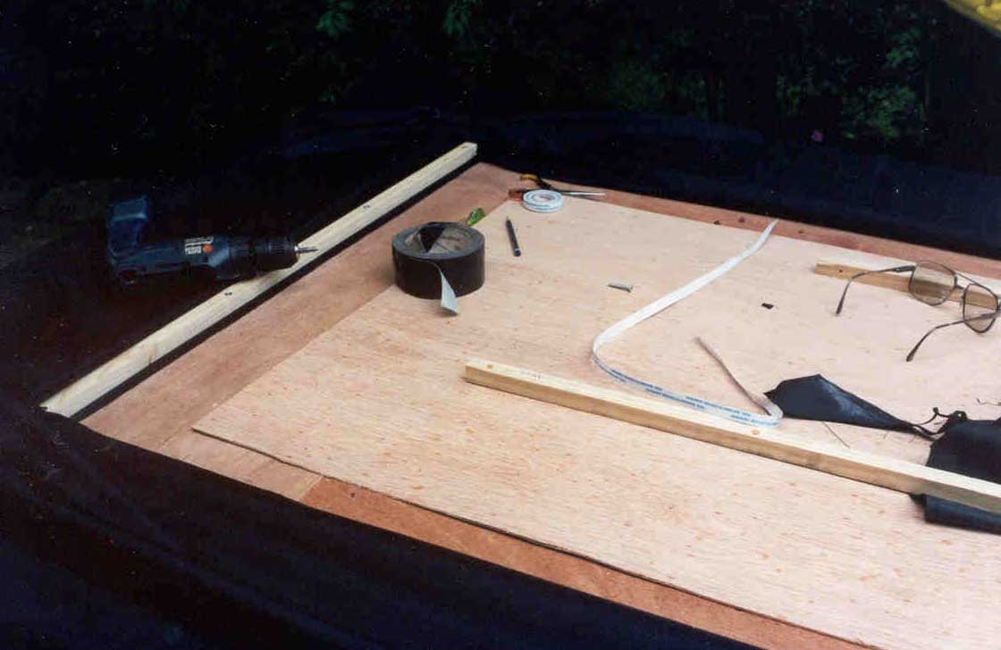
The construction method selected was a
pine frame with Luan Ply for the base.
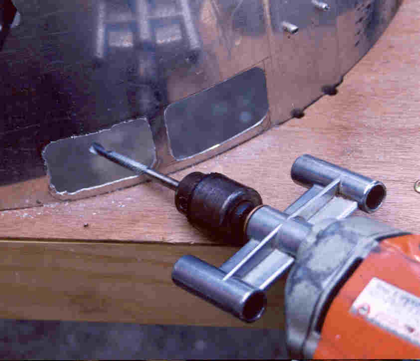
Aluminium was used for the lift duct since it was available, but
could be made from ply, although bending it at a 10” radius could be
difficult. A special
“bendy” ply is available, but could not be bought in a small enough
quantity to be economical.
Using a Hovercraft calculator obtained from the Internet
Created by Alex Olshove and available from www.rqriley.com )
a size of 5’ wide x 10’ long with all up weight of 300lb gave an engine power requirement
of about one HP.
This should be able to be easily provided by an ordinary lawnmower engine The frame was made from 70x19mm and 35x19mm pine. The skirt battens were 19x19mm.
only 70mmx19mm timber was purchased, the remaining widths were cut as required.
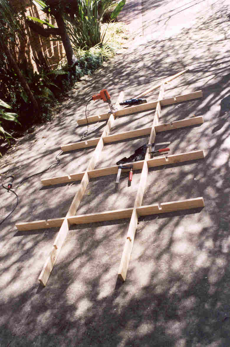
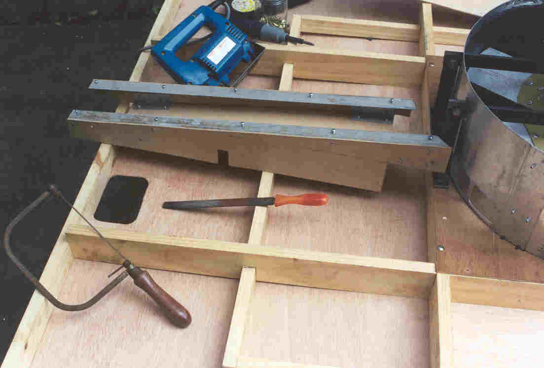
The backbone of the structure was the 70mm lengths, forming two longerons and 4 cross pieces.
An outer frame of 35x19 and skirt support of 35x19 completed the frame. All joints were screwed together
without glue to allow easy dismantling and changes should it be required, although the intention was to glue and
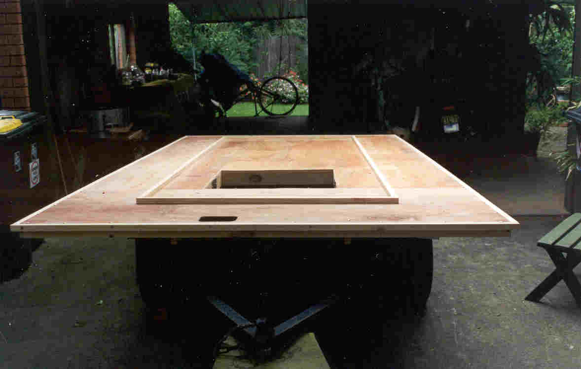
screw all joints, the frame so far has been rigid and strong enough with out gluing.. The frame was completed by screwing the base of 3 mm. Luan ply on the underside, cutting openings for the lift duct, and air feed to the skirt.
The luan ply was chosen because of its low cost and weight
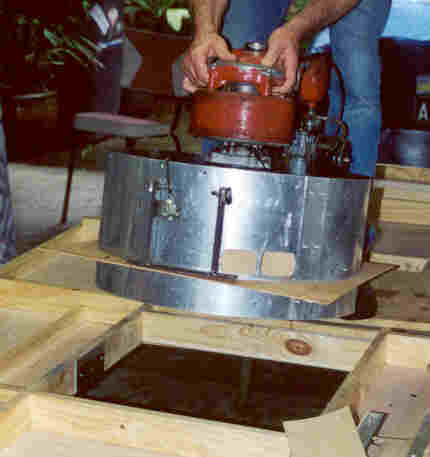
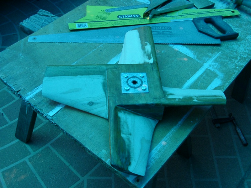
The lift system was made so as to be one unit which can be easily removable and comprises:
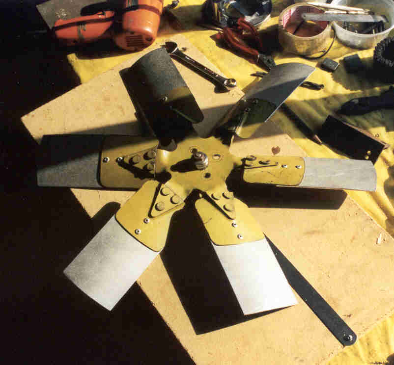
The original fan was based on the Renault 6-bladed car fan, adding a 4” extension to create a 20” Dia. fan.
The blades were curved thin sheet metal.
The performance with this fan was minimal, and in a effort to improve the lift performance, a new fan was
designed and made from wood. The angle of the blades on the old fan was 23 degrees, the new fan was made 32 degrees.
the new fan was made from pine, each blade was a separate piece fixed into an angled slot on the square hub.
The blades were streamlined to an aerofoil shape using a belt sander The wide rectangular blades prevented the engine from reaching optimal revs,
and performance was inadequate.
The blades were tapered and re shaped and engine revs returned to normal levels, but performance was only marginal over the metal fan. The skirt design was based on information taken from the Internet Website www.4wings.com.
This website includes a lot of information about hovercraft design and tips on construction including materials and skirt types.
It includes a section of designing skirts on which the skirt for this hovercraft is based.
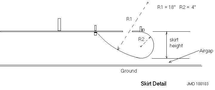
There are three basic types of skirts, the bag, Finger or segment and a combination of the two, the bag & finger. The simplest is the bag, This is inflated from the lift fan and can be either a no flow design, or a full flow design in which all the lift air flows
through the skirt and is fed into the underside of the craft by means of small holes on the inner skirt wall. The no flow Bag was selected for this project because of its simplicity. The cross section of the skirt is important to the
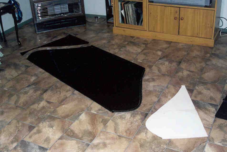
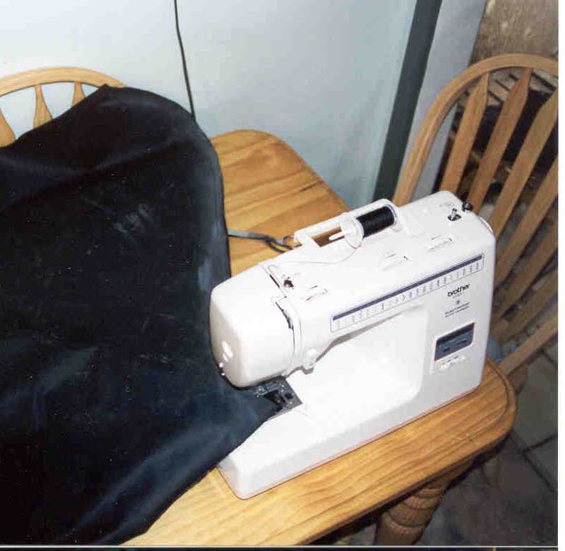
stability of the craft and this was based on the 4wings design information also. See diagram. The skirt was constructed from a PVC coated NYLON Fabric, one side PVC and the other a woven 420 denier NYLON.
This is inexpensive and meant for bags and satchels. It is reasonably wear resistant enough for light use.
The material was cut and sewn and joints sealed with a sealant. It was fixed to the frame using 1" square battens with contact cement to act as a sealant. Skirt inflation was provided by tapping air tangentially from the aluminium duct, and passing it to
the skirt by a MDF box duct terminating at a slot in the luan base.
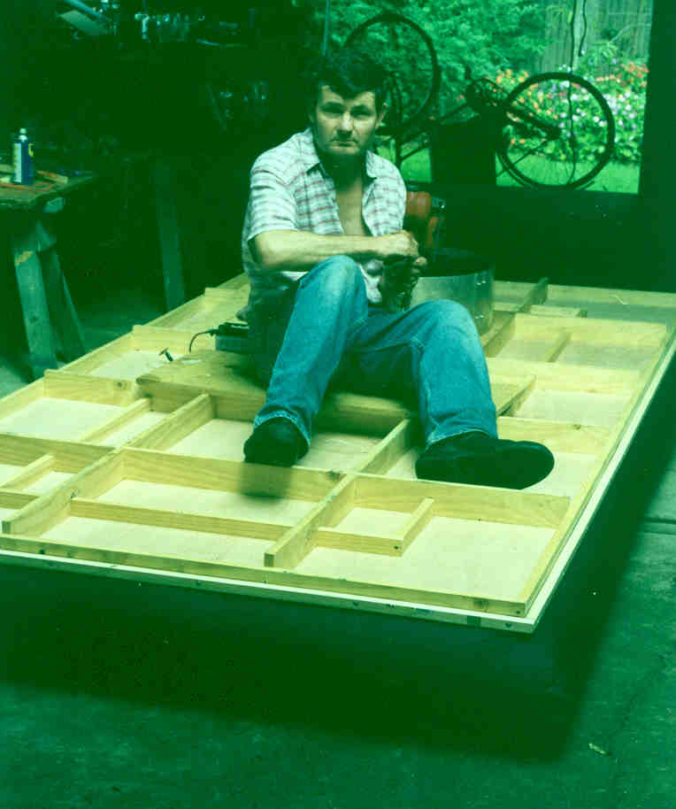
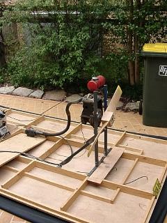
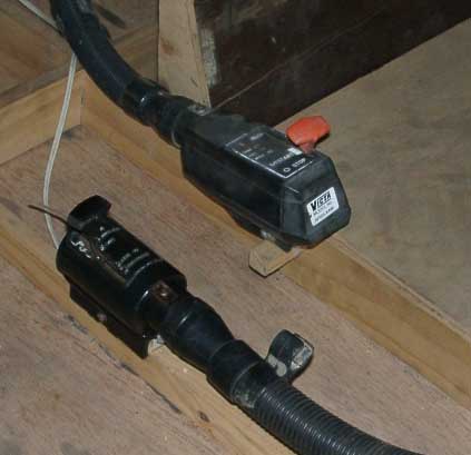
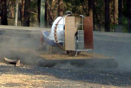
Stage 1 - Frame, base and lift system operational Without forward thrust the craft is useless. Another lawnmower engine with a propeller provides thrust.
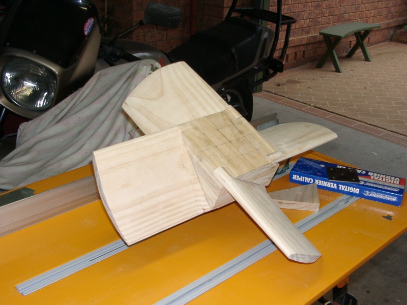
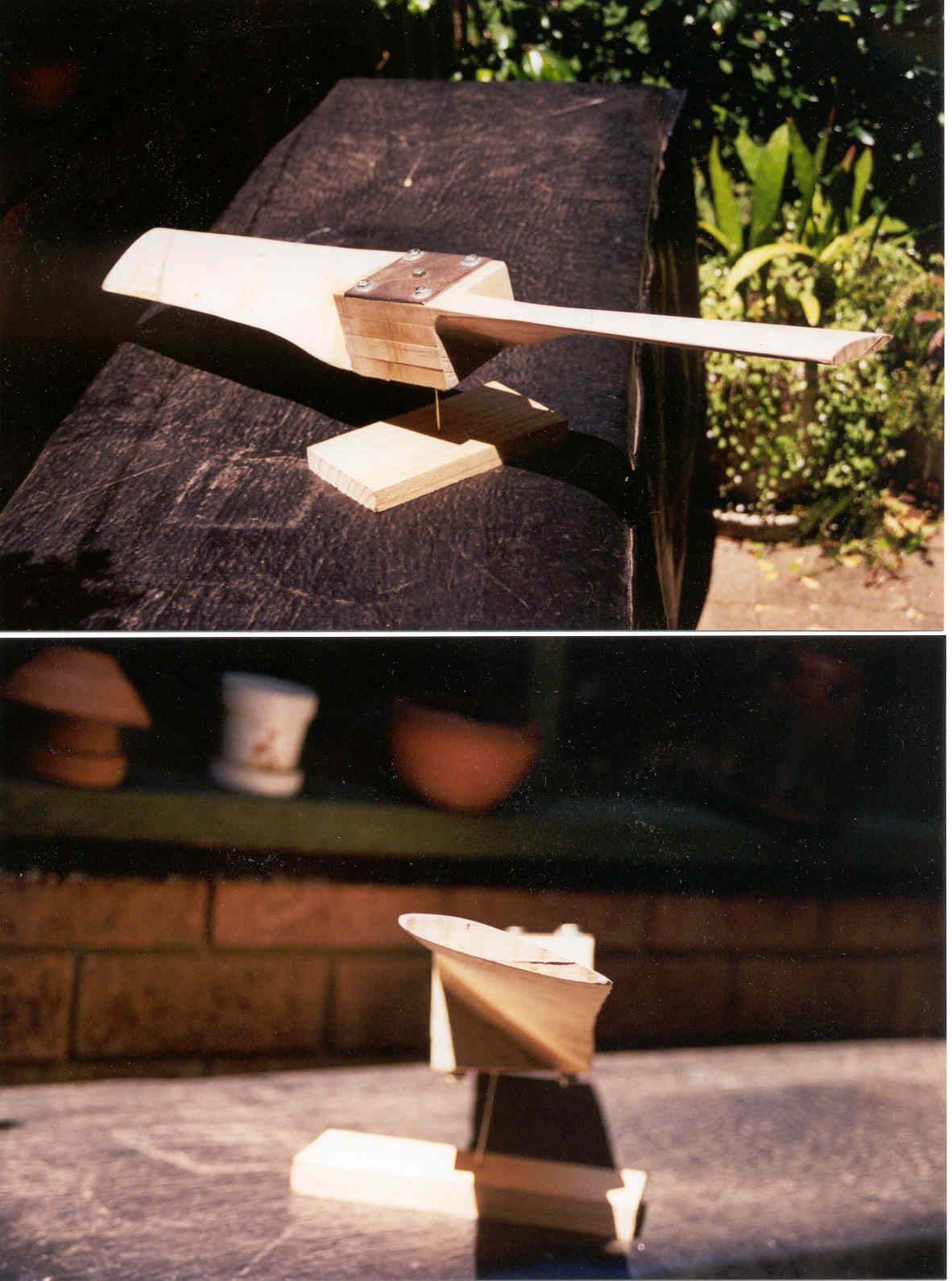
The propeller was carved from three layers Tasmanian Oak glued together.
The VBASIC design program JAVAPROP v 1.2 by Martin Hepperle found on the Internet (Note: This document was found on the
Web at sites http://beadec1.ea.bs.dlr.de/Airfoils/ and http://members.tripod.de/MartinHepperle/Airfoils/ ) This was used
to design a propeller for the thrust engine. Selecting a diameter of 30” or 762 mm as being reasonable from a physical size
perspective, and assuming max revs at 2000, with a power of 2 HP, and forward velocity of 30mph the design details are:
Original design These were thought too optimistic with an unknown power lawnmower engine, and so for construction were changed to:
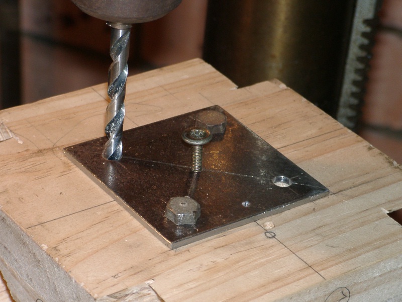
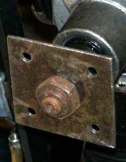
The propeller was fastened to the engine by bolting a 1.5mm steel plate to the propeller with a large enough hole in the propeller
boss to accommodate the engine nut and with sufficient space for a socket spanner. The same technique was used on the second lift fan
Both were balanced statically by balancing on a thin wire stake..
The thrust engine mounting was made from 6mmx25mm mild steel, and comprised a horizontal base
screwed to a frame cross member,
with two vertical uprights bolted to it. From each upright a brace piece angled forward and was bolted to
each longeron by a bracket that was attached with two screws. The engine was bolted to the uprights by appropriate sized tags welded to the upright. One upright also supports the fuel tank.
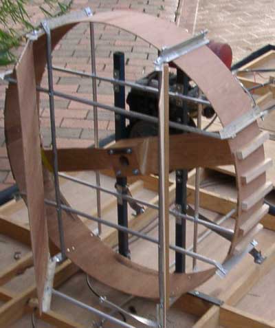
The propeller is shrouded by a ply shroud approx 150mm wide, which is supported by an aluminium tube matrix.
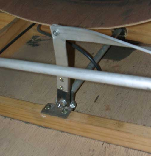
The matrix is bolted to the engine uprights and it also supports the rudder pivots. The controls comprise a joy stick with lateral movement only to operate the two rudders.
The movement is transferred by a torque tube running under the seat and a lever arm attached at the rear.
Basic design
Total design details are:
Dimensions Weights
Width
5'
Ply Base
35 lb
Length
10'
Frame
5 lb
Air gap under skirt
0.5"
Lift Engine
30 lb
Gross weight
300lb
Thrust engine
30 lb
Cushion Pressure
.046psi
Pilot
170 lb
Expected air velocity
46.8 ft/sec
Skirt
15 lb
lift Air Volume
52.6 CFS
Misc
15 lb
lift HP required
1.06
Lift Fan Dia
20"
Total
300lb
The Frame
The lift system
Engine mounting
The engine frame is made of 3 major parts.
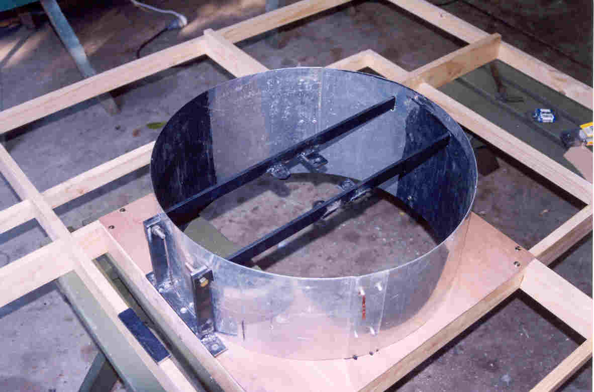
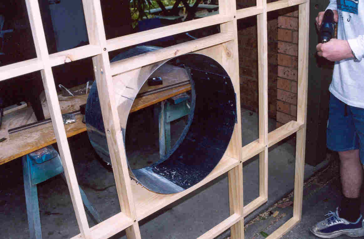
The Duct
The Duct was made from aluminium as it was available, but it could be made from ply. A special "Bendy" ply is available.
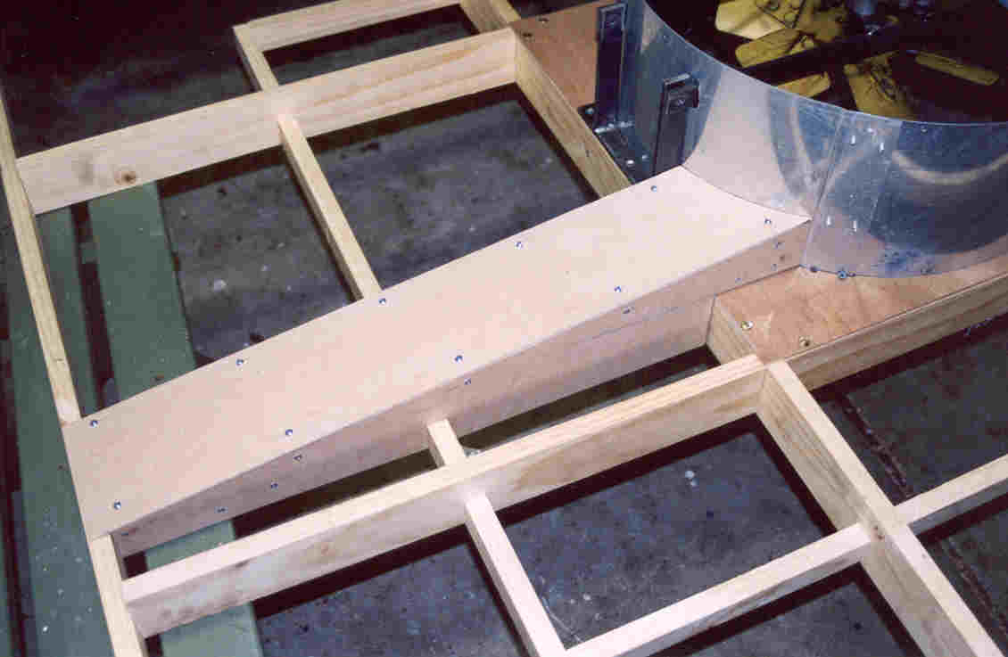
The engine has a welded mild steel mounting frame, which passes through slots in the duct and is screwed to the cross members
The Duct passes down to the bottom of the cross members and is held by 4 screws in the square made up of the two longerons,
one main cross member and a supplementary cross piece. A ply cover cut with a circular hole supports the duct and seals the gaps
between the circular duct and square opening in the frame.
The Fan
The Skirt
Shirt inflation
Propulsion system
Thrust Propeller design
Geometry
The calculator gave a large angle of attack at the spinner which would have required a very thick root.
Therefore, the design was manually adjusted to minimise the angle to about 30 degrees at root. T
he propeller could then be made from 4” wide x 3” thick timber 30” long.
Manufacture was carried out by gluing 4 layers of 4"x3/4" pieces together, and marking the leading edge
and trailing edges by measuring down from the flat face. Saw cuts were made to these lines and the excess material
chiselled away.
Finally a belt sander was used to clean up and round out to the smooth aerofoil section.
Thrust engine mounting
The seat and controls
 The lever arm is linked to one rudder, which is, in turn, linked to the other.
Copyright John M Douglas