My old car was a 1988 Mazda RX-7. Some people
call their RX-7s "their baby", but I would have called it "Rosemary's Baby". Every braking component on this car except the tubes has phoqued up
(those were replaced before I got the car), the master cylinder twice; Everything aft of the exhaust manifold broke, came apart, or just came off. The alternator, sunroof, clock,
HVAC control, fuel lines, power antenna, power windows, oil control rings,
synchronizers, starter, auto-adjusting suspension, speed-sensitive steering,
all have failed. One of the mufflers blew up. And spark plugs are
twelve dollars each.
The rotary engine draws in air and expels exhaust through "ports" on
the periphery of the rotor's path that are opened and closed in the same
way that similar ports are opened and closed in a two-stroke per cycle motor.
The rotary is, however, a four-stoke per cycle motor. There is normally one
intake port on each side of the rotor, one in the centre housing and one
in the end or front housing. Two rotors per engine are why there are "4 ports".
The "6-port" motors have one additional port per each rotor, so there is
a "5th" and "6th" intake port, if you're counting them all. This is in my
never-so-humble opinion is a stupid and confusing way to identify the engine
by something that doesn't work right, and most folks describe wrong. It is.
Now, the question "why did they have to make it so complicated?" is so frequent
a question for the RX-7 that the answer is probably in the Owner's Manual,
but some previous owner of my car didn't leave that for me.
The rotary engine in this car uses the rotating window valves in the intake
path, exposing the extra intake ports that open a path parallel to the main
intake ports. The intake charge should ideally enter
the motor at some fixed velocity, about 0.6 Mach. Obviously, since
the intake path is of fixed cross-sectional area, as engine speed increases,
this velocity will increase. As we know from Bernoulli and Reynolds and fluid
mechanics, (1) when the fluid velocity increases the boundary layer friction
at the pipe walls increases with the square of velocity; and (2) similarly
when the fluid has to negotiate bends through the intake ports the energy
losses there also increase with the square of velocity. So. At high
fluid speeds some of the engine vacuum is used as power to overcome these
increasing losses, so you get a less efficient air path than you really want
(see Paul Yaw's article at the end of this page and
http://personal.riverusers.com/~yawpower).
Enter the parallel 6-port design idea.
At low RPM these ports are to be closed for the intake air velocity to be
where it should be, for good inertia and torque development. If they were to stay at
this cross-sectional area the air path would make this engine kinda flat
after about 3500RPM, so these parallel paths open to give the air more
cross-sectional area and an easier way into the engine to let the velocity
stay in the good zone, and keep torque at this engine speed good. The rotary
operates really well at high engine speeds, so this whole setup keeps you
both content and smiling.
Please don't ask me complicated questions. Don't ask
me about port timing, because I don't know about it. I wrote this tripe because
I was tired of seeing people on the RX-7 list asking about this twice
a week. There's a lot of guessing, conjecture, shaky unsubstantiated
common knowledge that nobody can, will, or wants to verify, and a lot of
clueless unknowledgeable people giving "possible" answers or fully wrong
answers. I hope I can provide some background, maybe even some answers.
Now for the important tripe:
These port valves are operated by pneumatic linear actuators that turn a
bellcrank that rotate these window valves like a piston moves a connecting
rod that moves a crank shaft.. The early 13B models from 1984-1988 had their
pneumatic pressure source from the exhaust pipe, in the middle of the catalytic
convertor, where there was a pressure back-up high enough to make these actuators
work. Really, this pipe is used to give air to the convertor and is a convenient
and really the sole source of any positive pressure, from both the back-up
and from the air from the air control valve that feeds the convertor. I think
the idea is for them to start opening at 3800RPM and be fully open at 5000RPM,
as designed by the company. Problems can happen to people when they modify
their exhaust without any engineering for this pressure source. When
the pressure drops in the system are lowered or eliminated, by replacing
the mufflers, or especially by eliminating the catalytic convertor, the pressure
at this pipe could low enough so the actuators don't work. Then your top
end goes flat.
There are some who have developed taps into their headers or exhaust pipes
that take advantage of the exhaust velocity pressure, like a Pitot tube,
to get high enough pressure. I didn't do that. There's a word at the end
of this tripe from someone who has, and I believe the headers Mazdatrix sells
and the Bonez race pipe have this thing figured out too. Rotary Performance
www.rx7.com was working on an adjustable
system. I don't want to spend any more money on this
F!@#&^
Car. Some figures I measured are at the
end of the page. Please read.
The later models from 1989-1992 used an electronically operated solenoid
valve that fed positive air pressure from the air pump to the actuators.
This opened them fully at 3800RPM. Short story. You could remove your entire
exhaust from the manifold and it would still work. You just couldn't get
rid of the air pump... and it would only be there for these port valves.
Lose that, then your top end goes flat.
In a car that has no convertors, I measured the pressure from this split
air pipe. The max pressure I could get from the split air pipe was 1.75psi
at redline, 1.85psi at 8000. this isn't enough to open new actuators, never
mind decade-old arthritic actuators. Spec on these is 1.2psi to start to
open them; 2.1psi to fully open them. Then I measured pressure coming out
of the ACV vent and found to my delight that it's venting at exactly 3800RPM.
Perfect. 1.5psi. Why this I don't know (but it does fully vent at full throttle).
With both solenoid connectors disconnected the same thing happened. I can't
lose.
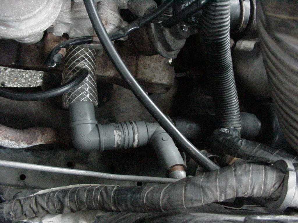
Use the tube coming off the ACV vent that connects to the silencer thing
that hides in the front right fender. Drill a hole in the tube the same size
as the factory black rubber tube and squeeze it into the drilled hole. The
factory rubber hose must be placed immediately after the vent and before
anything that might restrict pressure.
 I used 1" ID hose (2"-3" long) coming off
the ACV vent, a 3/4" PVC elbow, a 1/2" PVC Tee with 1/2" capped copper pipe,
and 3/4" ID hose that connects to the silencer thing that hides in the front
right fender. The Tee jammed right into the elbow (Perfect.) and the 3/4"
ID hose connects the tee to the silencer thing. Drilled a hole in the 1"
ID tube the same size as the factory black rubber tube and squeezed it into
the drilled hole. The hole drilled is smaller than when
I drilled it, and the hose stays in it. The plumbing fittings and hoses,
although narrower than the car's vent hoses, don't back up pressure by any
measurable amount, and the two silencers don't back up pressure enough. I
had to trial-and-error how far to jam the copper pipe into the Tee's straight
air path to restrict the flow enough to make the actuators move when the
ACV vents. This is because I am uber-cheap. Don't do that, do this: a) do yourself
a favour and treat yourself to a plastic ball
valve ($4) where you buy the plumbing fittings, or an electrical box wire/conduit clamp ($1 max, maybe you have a dozen in the garage), or use a hose clamp ($0.6). You can then pick the right restriction by holding the throttle at
the point where the ACV vents and turn the valve/squeeze the outlet hose until the actuators
move. The really picky can pick the sensitive point where the actuators will
only start to open at 3800RPM and be fully open at 5000RPM. I'm not that
picky. You're done. Congratulate yourself.
I used 1" ID hose (2"-3" long) coming off
the ACV vent, a 3/4" PVC elbow, a 1/2" PVC Tee with 1/2" capped copper pipe,
and 3/4" ID hose that connects to the silencer thing that hides in the front
right fender. The Tee jammed right into the elbow (Perfect.) and the 3/4"
ID hose connects the tee to the silencer thing. Drilled a hole in the 1"
ID tube the same size as the factory black rubber tube and squeezed it into
the drilled hole. The hole drilled is smaller than when
I drilled it, and the hose stays in it. The plumbing fittings and hoses,
although narrower than the car's vent hoses, don't back up pressure by any
measurable amount, and the two silencers don't back up pressure enough. I
had to trial-and-error how far to jam the copper pipe into the Tee's straight
air path to restrict the flow enough to make the actuators move when the
ACV vents. This is because I am uber-cheap. Don't do that, do this: a) do yourself
a favour and treat yourself to a plastic ball
valve ($4) where you buy the plumbing fittings, or an electrical box wire/conduit clamp ($1 max, maybe you have a dozen in the garage), or use a hose clamp ($0.6). You can then pick the right restriction by holding the throttle at
the point where the ACV vents and turn the valve/squeeze the outlet hose until the actuators
move. The really picky can pick the sensitive point where the actuators will
only start to open at 3800RPM and be fully open at 5000RPM. I'm not that
picky. You're done. Congratulate yourself.
You have the choice of placing the valve in the 3/4" ID tube where it makes
logical sense and easy to pick the closing position, or, if you want,
less work is involved by instead drilling into the factory vent hose and
placing the valve at the end of the vent tube under the right fender where
you'll need someone to hold the throttle when picking the valve closing position.
I couldn't do this because when I put the fender back on the car (none of
your business) I forgot to put the hose bacon the plastic silencer.
Alternately, tap into the vent hose, and cut out enough to put the valve after this. Use some of the cut section to reconnect to the silencers, or maybe replace the first silencer with the valve - I still think the exit location ahead of the wheel under the car masks the noise the most.
With this contraption on the car the motor is good until 3500RPM, a little
flat from 3500RPM to 3800RPM, then there's a little boost there and the exhaust
tone changes to a little bit of a higher pitch, and the engine is lively
until nearly 5000RPM, thereupon the secondary injectors put lots more fuel
into the air and give it a big boost. My little flat spots might be a result
of more flow and port velocity from having empty catalytic convertors on
the car. I didn't say I was an expert.
-
http://www.geocities.com/MotorCity/Downs/9299/projects.html
-
Scott Stachiw,
[email protected], The RotorManiac,
took the ACV vent tube and funneled it into a valve, backing up pressure
to open the ports wherever he liked. Gives excellent explanations, diagram.
-
-
http://home.earthlink.net/~burntoast/6port.html
-
Travis Shrey [email protected] has
a set-up that is something between Scott's and Buzz's. Travis' page has lots
of information on other modifications, and also provides lots of background
knowledge from an obviously very knowledgeable person. When someone on the Team FC3S NA message board asked the 6-port question and I answered "Oh, I have something to read" there would be twelve messages backing up Travis' web page. Weird. I'm trying to gracious to say I disagree that just hooking up an air line to the air pump doesn't work properly.
-
-
You can do what Buzz Bloyer
[email protected] does:
-
"I have an 87na with headers. I pulled the vac line (between the 6 port
actuator and the split air pipe) from the spit air pipe and put it into the
large air pump to ACV hose. I then spliced the vac line with a fish valve
so I can delay the opening of the six ports."
-
-
Michael J. Fregoe [email protected]
offers these pearls:
-
Jason, here is an E-mail that I sent another person that should answer
your questions. E mail me back if you have any problems, and don't forget,
let me know how it works!!!
Mike
OK
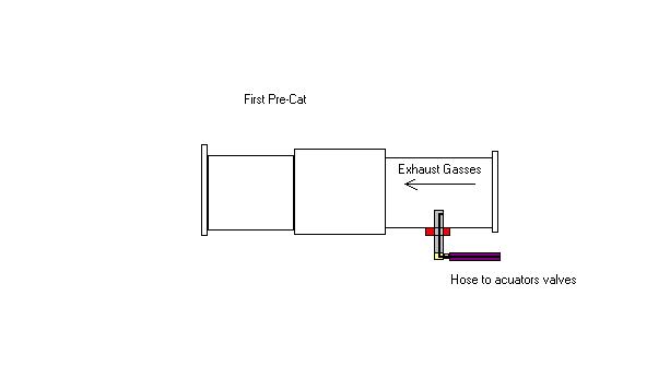
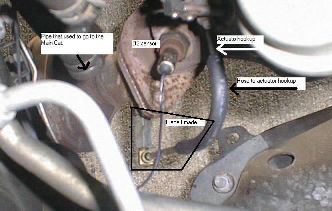
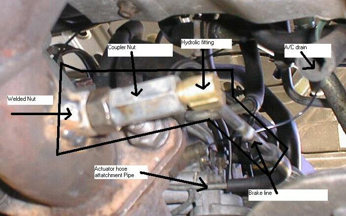
I had to make the necessary pieces and assemble them.
I used a stainless steel 1/2 inch bolt (4 inches long total that had 2 inches
of thread) and cut the head off 1.25 inches above the threads. I then drilled
into the side of the bolt with a 1/8 inch drill bit HALFWAY THROUGH the bolt.
I then drilled longways into the bolt from the thread end until the two holes
met. REMEMBER because of the extreme heat of the rotary use only stainless
steel! I then selected a nice spot on the pre-cat and drilled a 1/2 inch
hole 2 inches back from the front flange. I screwed a nut on the piece and
inserted it into the hole and had the NUT only welded in place on the pre-cat.
I positioned the inlet hole around 1/3 of the way into the inside of the
exhaust pipe. Position the hole so that exhaust gasses coming out of the
engine go into the hole you drilled into the bolt. Get a 1/2 inch to 3/8
coupler nut and drill the 3/8 end to 11/32 and tapped the hole to accept
1/4 inch pipe threads. I then installed some new metal brake line into a
90 degree fitting I bought at NAPA. I cut the brake line 6 inches long and
attached the line that goes to the actuators.
The reason for the brake line is that the exhaust gets so hot that the rubber
line will MELT without some kind of stand off from the exhaust piping. Mine
just happened to open about 3600 RPM under load. The mazda spec is 3600-3800.
(Michael has three pictures of his contraption)
There are other ways to do it that cost more money. see the link below.
http://homepage.mac.com/jburger/jaysrx7/6PortSolution/
-
-
Like Michael suggests, read what Jason Burger
[email protected] made. That Jason uses
good diagrams and has a good web page. Do you love those trendy 70s names?
I do.
{FAQ on}
-
What are 6-ports?
-
Those are the auxiliary ports in your beloved rotary engine that let more
fuel/air into the engine at high RPM and at longer and later duration of
the rotary stroke. A detailed description is above on this very web page.
-
-
Why don't my 6-port actuators work?
-
I don't know.
-
-
Will a system with no cats open the 6-ports?
-
I don't know. Probably it won't. You'd have to measure the pressure or listen
for the bump in exhaust tone.
-
-
Will my aftermarket exhaust open the 6-ports?
-
I don't know. See above answer.
-
-
What the hell is a fish valve?
-
A little fitting for aquarium air lines that connects in the air line, with
a screw in it to partially block the air line to regulate outlet pressure,
for a smaller or bigger train of bubbles in the fish tank.
-
-
How do I test the line pressure and/or actuation of the actuators?
-
To see if they work at all, put some grease at the bottom of the actuators'
shafts, then after running the car, see if the grease is smeared up the shafts.
This will tell you if they moved, but not when. You may be able to notice
when, but that is not likely, especially if you don't know exactly what to
look for. To know for sure you could use this other method:
Find 1/8" flexible vinyl tubing, a 0-5psi pressure gauge, and a 3-way 1/4"
tee. You can find these tees easily at a pet store ($2) next to the fish
valves ($3). They are also available for plumbing, but those ones are hard
to find. Plug the vinyl tube from the tee to the manifold tube, and from
the tee to the gauge, and from the tee to the pressure source (be it split-air
tube or ACV relief or ACV feed or exhaust tap). Have the gauge in the car
and read the pressure as you operate the motor through RPM at different load.
Use a minimum of second gear. You'll see if you have enough pressure to drive
the actuators, and if there's a small dip or flat in the gauge rise, that
should be when the actuators move. Note: I never saw any dip or flat at all
but my 2 conditions were either definitely too low or definitely working.
Also read Paul Mullen's page
http://home1.gte.net/pmullen/thePeritrochoid/epi/firstGenTechs/sixPortTest.html.
-
-
Could I use the feed from the air pump to the ACV for these?
-
I guess you could, and some people do. When I measured the pressure in that
line its output was changing all the time. It rose from about 1.5psi at idle
to 2.5psi at 2500RPM and stayed above 2.5psi after that speed as long
as the throttle was partially down. At no-throttle engine braking
the air must be diverted into one of the emissions control streams because line pressure shot to gauge max. At
minimum-throttle cruise pressure was about 1psi and at full throttle
the vent dumped all the pressure and I got 0psi, right on the peg
- then this closes the ports (bad). Without some kind of reducer they were
open in virtually all driving. You could probably make this work for you,
but I turned away from that idea when the ACV vent worked like a dream, an
unadjustable dream.
-
-
Will using too small a tube delay or stop opening of the port valves?
-
No. The smallest point in the path is the brass banjo bolt connecting the
metal tube to the manifold. It has a 1.0mm hole drilled through it that each
actuator's air passes through. They don't need to move a lot of air to work.
This is also where the bolt fails, so don't overtighten it.
-
Why don't my actuators work when I rev the engine with the car parked?
-
To get enough flow for backpressure the car needs to be fed lots of air and
gas, and that doesn't get to happen unless you're under the load of already
going fast enough.
-
-
Enough talk. How about some numbers?
-
When I had two mufflers on the car, I got a highest of 1.75psi at 7000RPM and
1.85psi at 8000RPM. Now that I have gone to a one-muffler setup (Bosal), I get these results:
| RPM |
2500 |
3000 |
3500 |
4000 |
4500 |
| 1 |
1.3 |
1.3 |
1.6 |
2.0 |
2.5 |
| 2 |
1.3 |
1.5 |
2.0 |
2.5 |
2.75 |
| 3 |
1.3 |
1.5 |
1.75 |
2.5 |
2.75 |
| 4 |
1.25 |
1.4 |
1.75 |
2.5 |
3.0 |
| 5 |
1.0 |
1.5 |
2.0 |
3.0 |
>3.0 |
I'm not certain what numerical effect having two mufflers dividing the pressure
actually had, but the effect of the muffler system on this tube pressure
looks substantial. This chart suggests that everything will work real
good without catalytic convertors, and one run-of-the-mill 2-tube semi-performance
aluminized steel muffler. The gauge also read totally different numbers at
3 throttle states: cruise, accelerate (~1/4 to 3/4), and full throttle. Cruise
wouldn't breach 1.0 psi or 1.2psi, accelerate gave the numbers here, and
pressing the throttle farther put 1.0psi -1.5psi more. The numbers in first
gear are as not as precise the other gears but show the same pattern. Most
notably in this gear more than the others I read over 2.0psi with very heavy
throttle at anything over 2500RPM. That's so inaccurate. When the 5000RPM
secondary injectors work the pressure usually jumps to 4.5psi or 5psi. I
didn't need to measure these to show what I wanted to show. Much to my surprise
(and chagrin) it looks like the thing will work anyway. I'd love to see someone's
dual muffler car put up some numbers, indeed I was a bit disappointed that
one of my mufflers blew up before I could have done any measuring. Still,
I wasn't very impressed by the way the numbers varied with the throttle because
you don't have full control over the intake port with engine speed, which
I think is the point behind variable valve timing. Honda's and Toyota's variable valve timing are only
RPM-dependent. The effect on the 1984-1988 RX-7 depends on what convertors,
mufflers, filters, compression, foot you have. Everything is a variable.
That's not how you design things!
-
{FAQ off}
Date: Sun, 11 Jan 1998 03:52:29 -0500
From: Paul Yaw
To: [email protected]
Subject: (rx7) [misc ] little round motors
On January 6, I sent e-mail to 36 members of the rotary webring to see what
kind of response I would get. It seems that a few of the recipients forwarded
my message to members of a mailing list. By the next day, I was swamped with
e-mail, asking lots of questions. I am having this distributed as well, and
I hope to answer all of these questions. To those of you who responded, I
would like to say thank you.
Now here goes with the answers. First off, what I am doing is not new technology.
It is existing technology being applied to rotaries. Airflow development
has been an integral part of piston racing engine development for about fifteen
years. It is mostly responsible for the major power increases that we have
seen in piston engines since the seventies. In the past, rotaries had a huge
power advantage over the piston engine. This advantage has been slowly lessened
as a result of airflow development with the piston engines. General Motors
acquired their first flowbenches in the seventies, and now most of the major
manufacturers include this in their engine development programs. The results
are obvious, as we keep getting more horsepower from less displacement. I
seriously doubt that Mazda has given this much thought, at least up to and
including the 6-port motor. This was a wonderful idea that was very poorly
executed. These motors have very poor flow efficiency.
With the exception of the ignition system, almost everything that we do to
make more horsepower, is the result of an increase in airflow. The amount
of horsepower that any engine can make is directly proportional to the amount
of air fuel mixture that the motor can ingest. For the sake of brevity, from
here on out, I will refer to the air fuel mixture as simply air.
It only makes sense then, that every part of the engine should be optimized
to flow as much air as possible, consistent with high velocity. Velocity
alone determines at what rpm peak torque and horsepower will occur for a
given port timing. As most of you know, the intake ports in a rotary engine
close well after bdc (bottom dead center). What this means is that the port
is still open when the rotor begins to compress the air. At low rpm, some
of the air is forced back out into the induction system, thus lessening the
amount of combustible mixture in the chamber. As engine speed increases,
the inertia of the air rushing through the manifold will overcome the pressure
from the decreasing chamber volume, and will continue to pack air into the
motor well after bdc. This effect is known as inertial supercharging. You
can feel this when you are driving. When the motor revs up and really starts
to make power, you are feeling the effect of inertial supercharging. Now
it should be clear that maintaining velocity is critical.
The same thing happens on the exhaust side of the motor. The gasses exiting
the motor will leave behind a low pressure area, which helps to further expel
the spent gasses at the end of the exhaust cycle. In some cases, the chamber
will be left at a negative pressure after the exhaust port closes, and this
helps to start the flow of fresh gasses after the intake port opens.
Velocity is critical! The process of flow development involves increasing
the airflow, while maintaining high velocity. If the runners are simply hogged
out and made bigger, the airflow will usually increase, but THE VELOCITY
WILL ALMOST ALWAYS DECREASE. Because air has mass, it is affected by inertia,
and so does not like to change direction. A straight runner will flow a great
deal, but when a bend is introduced, airflow drops. The airflow is also disturbed
if the runner has large abrupt area changes. Proper porting involves removing
material from areas where the air "needs more room" and leaving relatively
stagnant areas alone. It is the shape of the passage that is important, and
making the radiuses as gentle as possible will greatly improve airflow. By
using a velocity probe while the ports, or manifold is flowing air, it becomes
clear which ares of the port need work, and which areas should be left alone.
Removing material from relatively dead areas of the port, will kill velocity,
and sometimes airflow as well. When I flow test a port or manifold, I start
by filling it with water to determine its internal volume. I repeat this
several times during the porting process, and compare this to the airflow
numbers. If airflow is increased more than the volume is increased, then
the velocity has gone up. If the airflow has increased less than the increase
in volume, then the velocity has decreased, and low rpm power will suffer.
In extreme cases high rpm power will also suffer.
It has been determined that once the velocity has reached .6 mach (60% of
the speed of sound) no more horsepower can be made. As the velocity increases
beyond this point, the pumping losses become too great, and the motor "tops
out" Velocity and airflow must be carefully balanced.
The first step in porting a motor involves cutting the intake ports. The
port timing is determined by the shape of the port window. I will not go
into this here, as everyone is familiar with street porting and bridge porting.
The airflow is optimized by shaping what I call the "bowl area" where the
air makes the 90 degree turn, and then blending it into the runner as gently
as possible. Years of testing have proven the correct shape, but I ruined
a lot of ports to get there. The correct shape is rarely obvious. In most
cases the runners need not be opened up. It is true that this will improve
airflow slightly, but at the expense of velocity. If it does need to be opened
up, it should only be widened on the long side of the port. Widening the
short side will hurt airflow and velocity. When the ports are done, and matched
front to rear, I take a final flow measurement, and this becomes the baseline.
The next step is to bolt the manifold to the motor, and see how much this
affects the airflow. In most cases, this will decrease the airflow by ten
to twenty percent. Since our port runner, (which is the point of minimum
cross sectional area) has not changed, but airflow has been reduced, we have
lost velocity. When we lose airflow and velocity, we lose power at all engine
speeds. The goal now is to increase the airflow of the manifold until it
no longer affects the flow of the ports. In some cases the airflow will increase
slightly with the completed manifold attached. If a carburetor is used it
will ALWAYS reduce the airflow slightly, but that is the price we must pay
for carburetion. If fuel injection is used, the throttle body should be sized
appropriately so that it does not decrease airflow.
Now that the entire induction system has been flowed, we can move on to the
exhaust ports. dyno testing over the years has show an optimum ratio of intake
to exhaust flow, which varies depending on port timing. I would prefer to
keep these ratios to myself, as I have had to build and dyno many different
combinations to find out what worked best. The ports are then cut to achieve
the correct airflow with the least amount of port timing. Keeping the port
open for the least time possible will help with low rpm power and fuel economy.
Needless to say, the exhaust port can only be optimized if the total flow
of the induction system is known. While the exh. port seems simple enough,
it has a huge effect on the characteristics of the motor. While it looks
like it must flow efficiently (it's just a hole in the motor, with no direction
changes)it has a coefficient of discharge that is no better than the intake
port, which makes a sharp 90 degree bend.(Coefficient of discharge is a measure
of the flow efficiency of a given orifice, with a venturi being the "perfect"
shape at 100%) The reason for this is the shape of the stainless steel sleeve
in the rotor housing. This sleeve creates a tremendous amount of turbulence,
and absolutely KILLS airflow. There comes a point during porting, when raising
the port roof actually decreases the airflow, even though the hole is bigger.
As an example, by removing the sleeve and reshaping it, the flow of a stock
12A exh. will increase by 29% without even touching the port! This is a very
good thing, since improvements in airflow are usually made a few percent
at a time. I used the 12A as an example, but all of the ports are bad. Removing
the insert on the 6-port motors actually decreases airflow. The stock port
is horribly inefficient, and when a motor is street ported it gets even worse.
This is most of the reason that ported motors have such poor low speed power.
On a street ported 12A, the increase from reshaping the sleeve is good for
almost 40%.
Efficiency is the key! Remember, anytime that we can increase flow, and velocity,
we will gain power at low, and high speed. High output rotaries do not need
to be peaky, hard to drive pieces of junk. My rotary pickup has a mildly
bridgeported 13B, and it is regularly used for towing. I hope that I have
cleared up any confusion, and would like to hear from everyone. I am sure
that I could learn a lot from all of you, and I do not mind answering questions.
(Assuming of course that I have the answer!)
I can be reached at
[email protected]. Happy motoring.
Paul Yaw
Yaw Power Products
Tucson, AZ
http://personal.riverusers.com/~yawpower)
(Paul can also be reached at
[email protected])
Paul talks about exhaust ports, Justin talks about exhaust systems. These
two peoples' collected works complement each other to explain most of how
the deal works.
Date: Wed, 8 Dec 1999 13:36:30 -0600
From: Justin Arnold
To: [email protected]
Subject: (rx7) backpressure
Alright.. gotta chime in on this one.
Backpressure is NOT what you want..
Velocity, is.
This is a very common misconception.
In general, people understand that when you are using a smaller exhaust (usually
on a natrually aspirated engine) you do gain some torque, and a broader power
band.. This is (in some cases) true, but it is not as a result of the
backpressure that it creates. what most people dont understand, is that the
higher torque and broader powerband are a result of the increased velocity
in the exhaust path.
Ill see if i can try and explain this one..
Backpressure, is simply a resistance to exhaust flow. A restriction. Basically
the engine has to use part of its power to PUSH the exhaust gasses out of
the combustion chamber and through the exhaust system.
A smaller exhaust, flowing the same overall volume of air, will have a much
higher "speed" to the air flowing through it. this air, as it is going faster,
will try and keep going faster, even between the exhaust pulses that push
it out.. The exhaust isn't usually one steady flow, but a extremely fast
series of rams that push it out. Anyway, if the speed if your air coming
through the exhasut is higher, then its inertia (which is much higher as
a result of the higher velocity (ie, a body in motion wants to stay in motion))
helps keep pulling it out between the pulses that push it out. In this case
you end up effectively sucking more exhaust out of the combustion chamber
than would be pushed out by the high pressure inside it alone. When you have
more exhaust gasses out, there is more room for fresh intake air and fuel,
and in effect, more power. The effects of velocity play a huge roll in the
working of the engine. For instance.. nearly all engines make more power,
as the revs climb, to a certain point. As the speed of the engine increases,
the velocity in the intake tracts skyrockets, and keeps ramming more air
into the engine than would normally be held, if there wasnt something pushing
it in.. This is called inertial supercharging. The thing pushing it in is
the air's own inertia that resulted from the velocity it gained when the
engine revved up and started sucking more and more air in.
When the engine stops making more power, and actually starts making less,
is the point at which the engine cant suck in any more air through the intake
tract. Another restriction.. In effect, the intake's version of backpressure.
This happens as a result of bad air flow, or simply too small of a path for
the air to go through, to increase the air volume flowed any more.
(Justin also links to Paul Yaw's web page)
Send email to
[email protected]


 I used 1" ID hose (2"-3" long) coming off
the ACV vent, a 3/4" PVC elbow, a 1/2" PVC Tee with 1/2" capped copper pipe,
and 3/4" ID hose that connects to the silencer thing that hides in the front
right fender. The Tee jammed right into the elbow (Perfect.) and the 3/4"
ID hose connects the tee to the silencer thing. Drilled a hole in the 1"
ID tube the same size as the factory black rubber tube and squeezed it into
the drilled hole. The hole drilled is smaller than when
I drilled it, and the hose stays in it. The plumbing fittings and hoses,
although narrower than the car's vent hoses, don't back up pressure by any
measurable amount, and the two silencers don't back up pressure enough. I
had to trial-and-error how far to jam the copper pipe into the Tee's straight
air path to restrict the flow enough to make the actuators move when the
ACV vents. This is because I am uber-cheap. Don't do that, do this: a) do yourself
a favour and treat yourself to a plastic ball
valve ($4) where you buy the plumbing fittings, or an electrical box wire/conduit clamp ($1 max, maybe you have a dozen in the garage), or use a hose clamp ($0.6). You can then pick the right restriction by holding the throttle at
the point where the ACV vents and turn the valve/squeeze the outlet hose until the actuators
move. The really picky can pick the sensitive point where the actuators will
only start to open at 3800RPM and be fully open at 5000RPM. I'm not that
picky. You're done. Congratulate yourself.
I used 1" ID hose (2"-3" long) coming off
the ACV vent, a 3/4" PVC elbow, a 1/2" PVC Tee with 1/2" capped copper pipe,
and 3/4" ID hose that connects to the silencer thing that hides in the front
right fender. The Tee jammed right into the elbow (Perfect.) and the 3/4"
ID hose connects the tee to the silencer thing. Drilled a hole in the 1"
ID tube the same size as the factory black rubber tube and squeezed it into
the drilled hole. The hole drilled is smaller than when
I drilled it, and the hose stays in it. The plumbing fittings and hoses,
although narrower than the car's vent hoses, don't back up pressure by any
measurable amount, and the two silencers don't back up pressure enough. I
had to trial-and-error how far to jam the copper pipe into the Tee's straight
air path to restrict the flow enough to make the actuators move when the
ACV vents. This is because I am uber-cheap. Don't do that, do this: a) do yourself
a favour and treat yourself to a plastic ball
valve ($4) where you buy the plumbing fittings, or an electrical box wire/conduit clamp ($1 max, maybe you have a dozen in the garage), or use a hose clamp ($0.6). You can then pick the right restriction by holding the throttle at
the point where the ACV vents and turn the valve/squeeze the outlet hose until the actuators
move. The really picky can pick the sensitive point where the actuators will
only start to open at 3800RPM and be fully open at 5000RPM. I'm not that
picky. You're done. Congratulate yourself.