1- Introduction to Frame Relay
Frame relay is a high-speed communications technology that is used in
hundreds of net-works throughout the world to connect LAN, SNA, Internet
and even voice applications.
Simply put, frame relay is a way of sending information over a wide
area network (WAN) that divides the information into frames or packets.
Each frame has an address that the network uses to determine the destination
of the frame.
The frames travel through a series of switches within the frame relay
network and arrive at their destination. Frame relay employs a simple form
of packet switching that is well-suited to powerful PCs, workstations and
servers that operate with intelligent protocols, such as SNA and TCP/IP.
As a result, frame relay offers high throughput and reliability that is
perfect for a variety of today's business applications.
A frame relay network consists of endpoints (e.g., PCs, servers, host
computers), frame relay access equipment (e.g., bridges, routers, hosts,
frame relay access devices) and network devices (e.g., switches, network
routers, T1/E1 multiplexers). Accessing the network using a standard frame
relay interface, the frame relay access equipment is responsible for delivering
frames to the network in the prescribed format. The job of the
network device is to switch or route the frame through the network
to the proper destination user device.
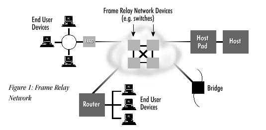
A frame relay network will often be depicted as a network cloud,
because the frame relay network is not a single physical connection between
one endpoint and the other. Instead, a logical path is defined within the
network. This logical path is called a virtual circuit. Bandwidth is allocated
to the path until actual data needs to be transmitted. Then, the bandwidth
within the network is allocated on a packet-by-packet basis. This logical
path is called a virtual circuit.
2 - Virtual Circuits in Frame Relay
Frame relay technology is based on the concept of using virtual circuits
(VCs). VCs are two-way, software-defined data paths between two ports that
act as private line re-placements in the network. While today there are
two types of frame relay connections, switched virtual circuits (SVCs)
and permanent virtual circuits (PVCs), PVCs were the original service offering.
As a result, PVCs were more commonly used, but SVC
products and services are growing in popularity. A more detailed discussion
of SVCs and their benefits occurs in Chapter 3. For now, let's discuss
the basic differences between PVCs and SVCs.
Using PVCs
PVCs are set up by a network operator whether a private net-work
or a service provider via a network management system. PVCs are initially
defined as a connection between two sites or endpoints. New PVCs may be
added when there is a demand for new sites, additional bandwidth, alternate
routing, or when new applications require existing ports to talk to one
another. PVCs are fixed paths, not available on demand or on a call-by-call
basis. Although the actual path taken through the network may vary from
time to time, such as when automatic rerouting takes place, the beginning
and end of the circuit will not change. In this way, the PVC is like a
dedicated point-to-point circuit.
PVCs are popular because they provide a cost-effective alternative
to leased lines. Provisioning PVCs requires thorough plan-ning,
a knowledge of traffic patterns, and bandwidth utilization. There are
fixed lead times for installation which limit the flexibility of adding
service when required for short usage periods.
Using SVCs
Switched virtual circuits are available on a call-by-call basis. Establishing
a call by using the SVC signaling protocol (Q.933) is comparable to normal
telephone use. Users specify a destination address similar to a phone number.
Implementing SVCs in the network is more complex than
using PVCs, but is transparent to end users. First, the network must
dynamically establish connections based on requests by many users (as opposed
to PVCs where a central network operator configures the network). The network
must quickly establish the connection and allocate bandwidth based on the
user's requests. Finally, the network must track the calls and bill according
to the amount of service provided. Although SVCs were defined in the initial
frame relay specifications, they were not implemented by the first carriers
or vendors of frame relay. Today, applications well-suited to SVCs are
driving its deployment. While PVCs offer the statistical bandwidth gain
of frame relay, SVCs deliver the any-to-any connectivity that can result
in network savings and flexibility.
3 - The Frame Relay Header and DLCI
Now that we know about virtual circuits, and the fundamental differences
between PVCs and SVCs, let's take a look at the basic structure of a frame
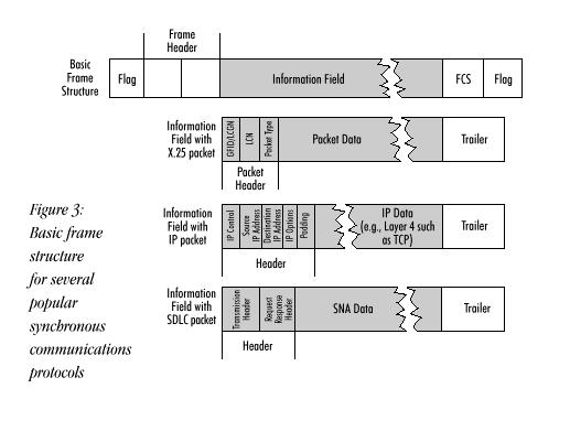
relay frame and how it accommodates other technologies. In the most popular
synchronous protocols, data is carried across a communications line
in frames which are similar in structure.
In a frame relay frame, user data packets are not changed in any way. Frame relay simply adds a two-byte header to the frame. Figure below shows the frame relay frame structure and its header in more detail.
For now, let's look at the largest portion of the header, the DLCI. The remaining six bits of the frame relay header are discussed after.
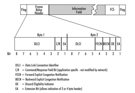
The frame relay header contains a 10-bit number, called the Data Link Connection Identifier (DLCI). The DLCI is the frame relay virtual circuit number (with local significance) which corresponds to a particular destination. (In the case of LAN-WAN internetworking, the DLCI denotes the port to which the destination LAN is attached.) As shown in next Figure, the routing tables at each intervening frame relay switch in the private or carrier frame relay network route the frames to the proper destination.
The DLCI allows data coming into a frame relay switch (often called a node) to be sent across the network using a simple, three-step process, which is shown as a flow chart .
- Check the integrity of the frame using the Frame Check Sequence (FCS) if it indicates an error, discard the frame.
- Look up the DLCI in a table if the DLCI is not defined for this link, discard the frame.
- Relay the frame toward its destination by sending it out the port or trunk specified in the table.
In order to simplify frame relay as much as possible, one simple rule
exists: if there is any problem with a frame, simply discard it. There
are two principal reasons why frame relay data might be discarded:
detection of errors in the data and congestion (the network is overloaded)
But how can the network discard frames without destroying the integrity
of the communications? The answer lies in the existence of
intelligence in the endpoint devices, such as PCs, workstations, and hosts.
These endpoint devices operate with multilevel protocols which detect and
recover from loss of data in the network. Incidentally, this concept of
using intelligent upper layer protocols to make up for a backbone network
is not a
new idea. The Internet relies on this method to ensure reliable communication
across the network.
For further documentation, please refer to Frame
Relay Forum.