Next round... May 3.
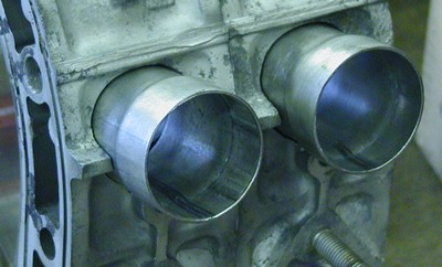 1.75"ID/1.75"OD exhaust tubing, cut to length. 1.5" of straight section on the smaller diameter, roughly 3/4" on the larger diameter.
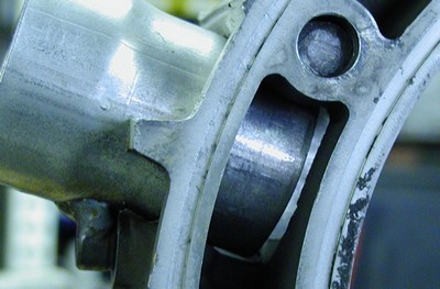
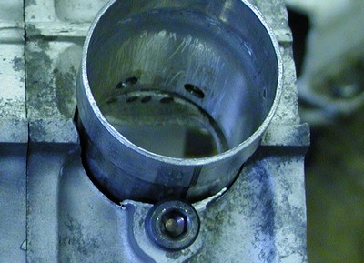 Strategic holes drilled, and a M8x1.25 Allen-head bolt cut to just the right length to apply some more squeeze to the tube. It's already a light press fit before the Allen bolt.
 Another shot of the Strategic Holes. Really just a gratuitous "I can't believe I'm pulling this off" shot...
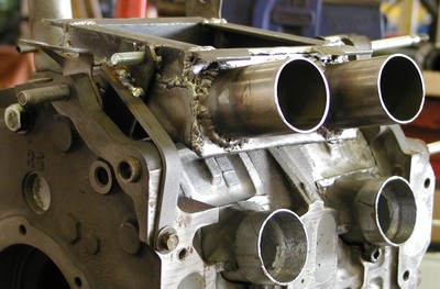
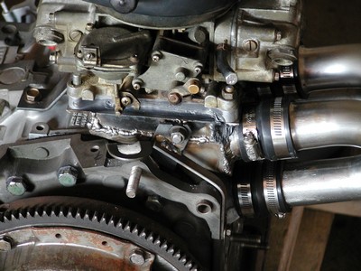
 Zap! Tubes welded to the Strategically Ground Bolt and to the pinch bolt. Ain't no going back now, boy, no there ain't no going back...
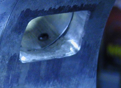
 This needs to be rectified.
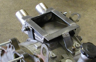
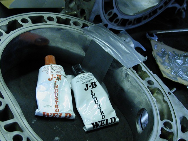 Did you know they made one pound tubes of JB Weld? Next time I'll bite the bullet and buy some Devcon. It only looks expensive until you realize that it took four pounds (two pounds metal, two pounds hardener) just to fill the old intake ports. Probably be another pound of each for the new intake ports. Live and learn. (The duct tape keeps the goo from free-flowing, and there is a plug in the intake tube to keep it from running out) The epoxy will also serve to help blend the round tube to the square aluminum.
May 24th, next sporadic update....
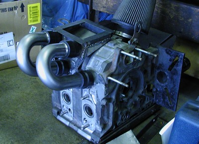
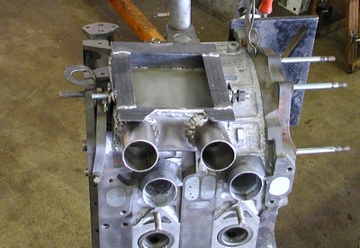
 Bare block shimmed up to the same angle as it sits in-chassis. The tubes are cut to the correct length and flared on one end for the intake manifold to spigot into. Intake manifold? Yes, we're getting to that.
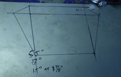
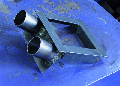 Intake manifold. Well, at least the makin's of a manifold. The angle-iron top plate was the first step, a simple job with some 1" angle iron, the rest was figured from that. 1 1/8" would have been better but space is *incredibly* tight. My goal is to fit the whole contraption under the stock hood. Anyways, those tubes are scavenged from cutoffs from the U-bends, and they are welded into 22 gauge sheet, after using the very same holesaw that was used on the rotor housings. I had lost my Welding Mojo and warped, scarred, and generally beat the hell out of the 22-gauge welding it together, but I was also overwelding it so I could port a radius into the tube entry. Distance between tubes at this point is 10cm center-center in order to get things level when it's on the engine. It also *happens* to be the same width as a Holley carb when measured outside-outside. Coincidence?
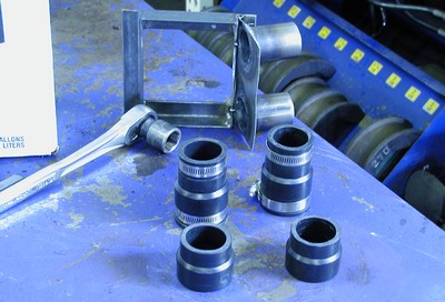 Shot of the underside of the manifold baseplate, and the absurdly expensive 1 1/4" - 1 1/2" PCV connectors. They cost FIVE BUCKS each. But, they will fit over the nude tube, and the oversized spigot.
 Drawing out the bottom cover. This one turned out to be 1/4" too small in all directions, for some cussed reason. I ended up cutting a too-big section out and whittling and figuring as I went. Kind of like the rest of this engine build. Planning just seems to be Bad Mojo.
 Radiused the tubes nicely into the "front" plate of the manifold... and wrecked it welding the bottom/side cover on. Oh well.
 Manifold on the tubes, all on the bare block. Progress, as I say, is progressing.
Update: June 10, 2005. Been way busy at work, hardly any time to think let alone think about the engine. The sticky wicket was just how to support the intake plenum. Then one day, in accordance with the rest of the engine project, I decided to just spend an hour with some metal stock and see what happened.
 Enter one small piece of 1 1/4x1/8 flat stock, placed as close to the port side of the engine (which, of course, is to starboard) to most support the port side of the plenum...
 ...Bolts welded to the plenum slot into the primary bracket...
 ...another angle, and a better shot of the additional mini-brace for the poorly supported rearwards end...
 ...and a simple strap to spoort the plugs side of the plenum. And done! Now we can disassemble the mocked up engine and finish the porting.
 Lot of JB Weld in the ports. And that's only the half of it. JB Weld dust is *nasty*.
Update June 13:
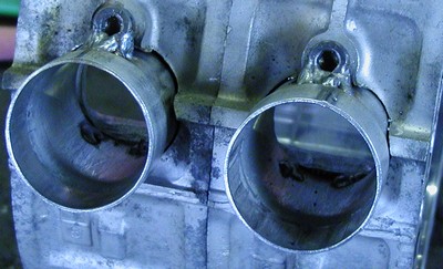
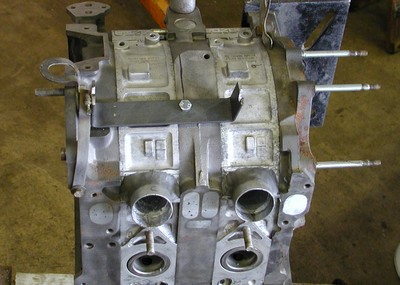
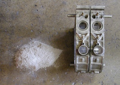
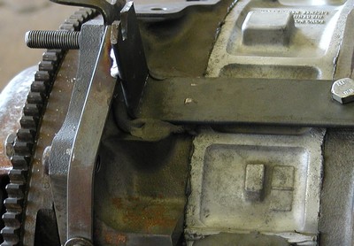
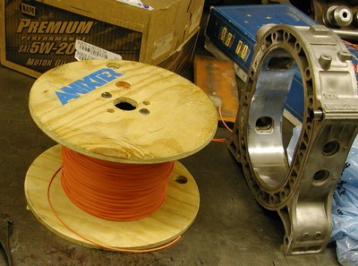 Special high-tech coolant seal material on the left. Okay, so it's 18-gauge hookup wire. But it's some fancy high-grade stuff my roommate got from work, we can't get it to melt. People have had good success with run-of-the-mill junk, so this should be overkill enough. Plus, it was free. On the right, we have a finished rotor housing. The intake ports look kinda bigger than I'd imagined. Oh boo hoo.
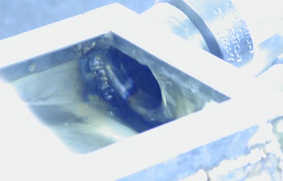
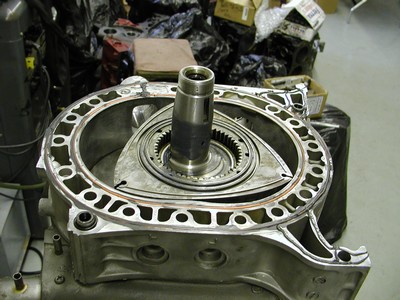 Time was of the essence during assembly, so this is the only real assembly-shot I've got. I spent five hours the prior night cleaning up the intake ports (JB Weld dust is *nasty*, especially when you're working in a 90-degree basement with no airflow) and only stopped when a sanding roll wobbled off, and with Warren Comission grade ballistics, bounced around until it went past my safety goggles and hit me square in the right eyeball. The white of my eye in that area turned pink, then red, and I decided to hit the sack. So in a nutshell, the next morning I had three hours to finish the intakes (mainly putting some seal-friendly bevels on the housing surface), clean the junk from the coolant seal grooves, relieve the epoxy in the coolant passages and the original intake ports, clean the bearings, clean the rotors and E-shaft, and assemble the mess. IN between all that I *was* able to take this picture. So there you have it...
Yes, that is RTV. Actually, it's Right Stuff brand sealant, which is loads better than your run-of-the-mill silicone sealant. It's more expensive (a little caulk-tube cost me $15!) but it is *the* best thing out there.
Update July 18 (no, really!):
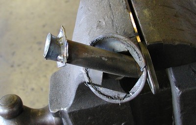 One pickup tube, screen cut out, back plate cut off, heated with torch and bellmouthed using the tool end of an old air hammer bit. Doesn't take very much heat to get the tube glowing orange! This was much less time consuming than brazing a bunch of material to the end and properly porting the tube inlet, yet still improves flow into the inlet a significant amount.
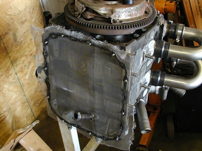 Yep, aluminum window screen. I figured, it'll slow pan slosh almost as well as a genuine baffleplate, and the mesh will help de-aerate the oil. Or it might have just been a waste of time. Didn't cost much, at any rate. Heavily siliconed to ensure I don't have pan leaks on *this* engine. Silicone should be sold as "turd polish".
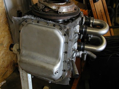 And , the oil pan is (finally!) installed. All that is left now is to make the throttle cable bracket and put it in the car. Except for that minor problem with the car being enbrokenated, ripped the rear upper links right out of the car last month. And so another project begins before the first one is ended....
Update July 20th:
 Paranoia creeps in. Some JB Stick Weld underneath that not-quite-supported-enough section of the plenum bracket.
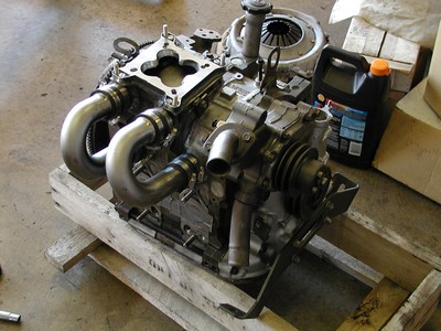 Trophy shot #537b. Engine is officially ready to be dropped into an engine bay!
 Shot of the backside of the engine, where you can see how that plenum is really crammed in there.
Home
modified July 20, 2005
Pete Remner aka peejay or sometimes ???