GEOMETRY OPTIMIZATION
Avaible Pages
JOB REF. CFD045246622
ABSTRACT
Sometimes I have cases of geometry optimization to reduce the pressure loss (CV increase).
When Pressure Drop is important and when you
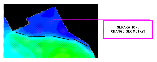
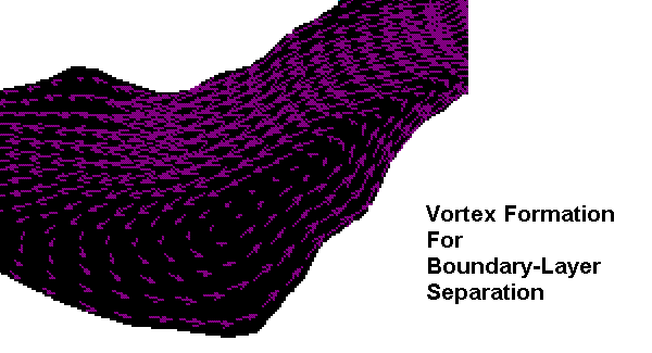
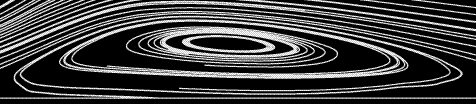
have boundary layer problems (boundary layer separation),
I like the k-omega model for the simulation of turbulence.
This sections contains a small description of boundary layer separation problems in case of Low-Reynolds-Number.
METHOD
K-OMEGA: As the model has been modifed over
the years, production terms
have been added to both the k and omega equations, which have improved
the accuracy of the model for predicting free shear flows.
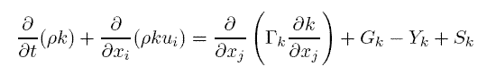
The equation are (see literature for references):
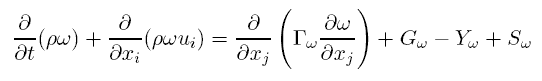
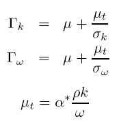
Where:
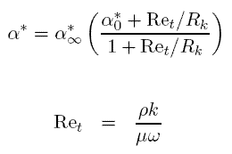
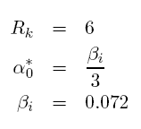
For some problems I have Low-Reynolds-Number, so that I use the standard correction:
INPUT DATA
|
DESCRIPTION |
VALUE |
UNIT |
SOURCE |
|
Conduit Geometry |
N.A. |
N.A. |
CAD |
|
Inlet Velocity |
varius |
m/s |
R&D |
|
Inlet Pressure |
varius |
bar |
R&D |
|
Turbulence Grand |
varius |
% |
R&D |
OUTPUT
CONCLUSION
CFD is becoming an important tool to compute
the flow field inside pipelines and conduits.
The Oil&Gas and the machinery industry is more interested in this technology,
because custumers are today more interesting for the equipment CV.
If automatic optimization is to difficult for
the industry and just the research at the university can do it, direct analysis
with manual
geometry change and iteration is the best way to reduce pressure loss and for
geometry optimization.