Home Page . . . . . . . Email: . . . . . . . . neelandan-at-gmãil·çöm
You might have a box full of nixies and wish to test them. This is a circuit to light all 10 digits automatically in sequence, using somewhat more than a ten-way switch and power supply. You have to rig up some sort of circuit to test them anyway. After you have tested all your stock this can be used as a demonstration display for nixies.
You might have just one nixie, and wish to display it. Well, why not an illuminated house number display using a single nixie? This works if your house number is less than nine digits long. For example, if your number is four digits long, break the asterisked connection and connect the reset input of the IC (pin 15) to output 5 (pin 1). Output 4 (pin10) is left free and outputs 0 - 3 connect via transistors to the appropriate cathodes of the nixie. For repeated digits, just connect the collectors together.
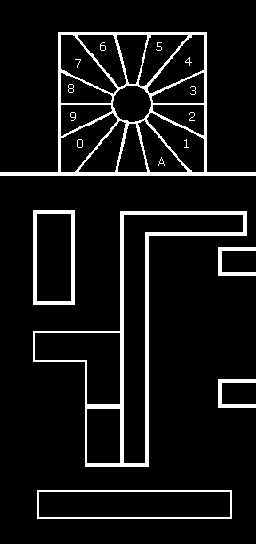
First off, I must say that this does not involve any drilling or etching to make the circuit board. All the components are mounted on the copper side, on lands isolated by cutting away channels using a sharp knife. Get all components together, lay them on a sheet of paper, draw around and decide what size the circuit board has to be. Then cut a piece of copper clad laminate board to that size. I built it on a board about 1.5 inches wide by 4 inches long. On it, the copper is cut away in narrow channels to isolate the lands for connecting components.
|
|
|
The board - cut to size and solder pads isolated - ready for soldering. Black = copper. |
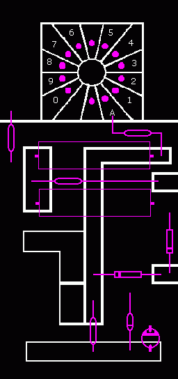
The tube socket and power supply components connected - ready for first test. |
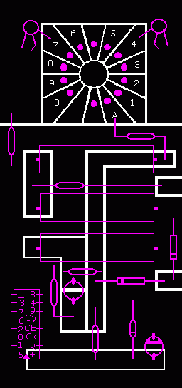
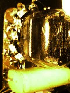
The integrated circuit and two transistors in place. |
Nixies usually have 13 pins. You will notice that the angle between them is such that there are 14 to a full circle with one missing. Place the nixie on the board, in the desired location, and draw the outline of the pads. Or print the figure and use it as a guide. Using a straight edge as a guide, draw the knife along the line to be cut. Draw another, closely parallel to the first line. You will then be able to peel away the thin strip of copper in between.
After the lands have been cut and isolated as shown you can start soldering: First, the tube socket. Buy a 25 pin D socket and take it apart for the tube socket pins. You will have enough for two tubes and some left over. Take 11 of those pins and fit on to the nixie and place on the board. Press and tap to make all 11 level. Solder diametrically opposed pins to start with and then solder all. It helps if you get the type of D socket with solder tails as these can be bent over parallel with the copper. Remove the Nixie, you do not want it to break during the rest of the operations.
Next, the capacitors, which are the next largest. There will be three for the 110 V version and two for the 240 V version. Place them on the board in the positions suggested, bend over the leads in a loop parallel with the board and solder. It helps if you decide on the places on the board which have to be soldered and tin these areas first. Using a too hot iron can result in the foil lifting off the board. If you refer to the layout you will get an idea of where the components fit in. Note that all components have not been shown.
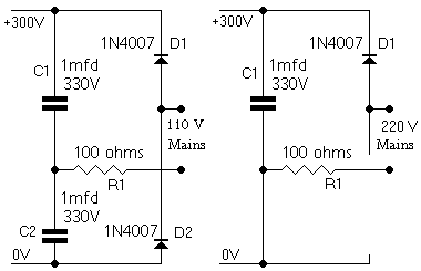
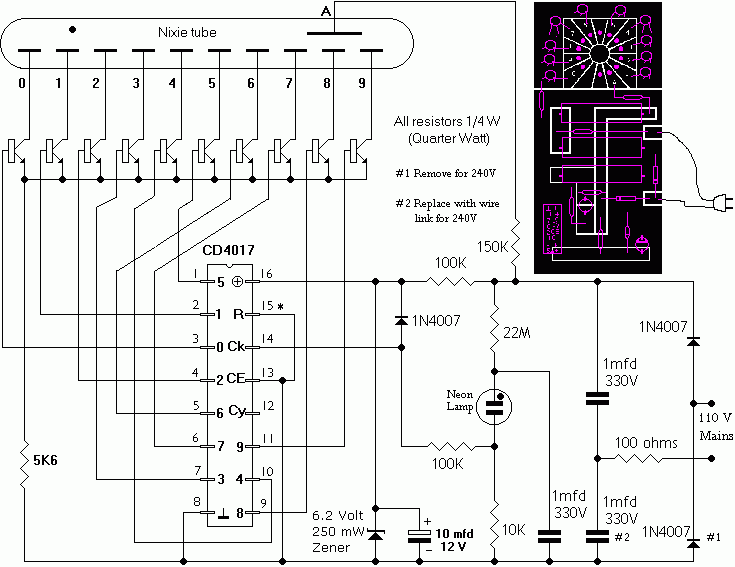
The figures show the two versions of that part of the circuit which derives the necessary operating voltage from the mains. If you have a 110 V mains, a voltage doubler circuit is employed. On the positive half cycle of the mains, C1 charges through D1 and R1 to about 150V. On the negative half, C2 charges via D2 and R1, again to 150V. The output is the sum of the two voltages: 300V. The resistor R1 has been employed as a kind of fuse, to limit damage in case of short circuit on the output.
If you are on 220 or 240 or 250 Volt mains, the circuit is a simple half wave rectifier. C1 charges to the peak of the incoming mains voltage via D1 and R1 limits current as before.
Solder up the power supply part and connect to the mains.
Switch on. If something does not go POP! with a bright flash of
light and a puff of black smoke, you are lucky. Measure the
output voltage with a multimeter. If it shows something in the
range of 250V to 350V the thing is doing its thing right, thank
your stars and move on to the next stage. Switch off, unplug and
place a screwdriver across the output to discharge the
capacitors. If you do not, you might receive a nasty shock!
Be warned.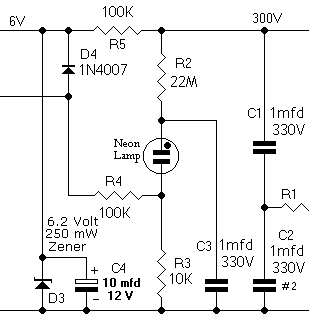
A neon lamp oscillator generates pulses to be counted by the integrated circuit counter. It rather ties in with the design because we have a large voltage available to make it work, and almost any other method of generating the necessary pulses will use up too much circuitry in comparison. The neon lamp also lights up the same colour as the nixie tube: they are built around the same principle.
For the next stage, you can wire up the neon lamp pulse generator and the 6V supply for the integrated circuit. Capacitor C3 charges slowly through R2 and when the voltage across the neon lamp reaches a particular value (the striking voltage) it conducts and emits light. It can conduct at a lower voltage (the maintaining voltage), once it has started. So the voltage on the capacitor falls and once it is below the maintaining voltage the neon lamp turns off and the cycle starts all over again. While it conducts, a current flows through R3, developing a voltage which is fed to the integrated circuit through R4. D4 serves as protection.
With R2, the neon lamp, C3 and R3 wired up, connect to the mains and switch on. The lamp should blink at a slow rate. This rate can be slowed down by increasing R2, or, if you want it faster, by decreasing R2. I could not get a 22Megohm resistor, so in my circuit R2 is actually two 10 Meg resistors in series. Once you have that working, switch off, unplug and place a screwdriver across the supply lines. Just a precaution.
R5, D3 and C4 drop the (high) voltage to the level necessary to operate the integrated circuit counter. Both D3 and C4 are polarised: they have positive and negative leads and must be connected the right way around.
Connect R4, R5, D3, D4 and C4, and power up. You should see that the neon lamp is blinking away and there should be a voltage of around 6V across the zener diode. If that voltage is around half a volt or so you have gotten the zener or the electrolytic capacitor the wrong way around.
Once all these check out okay then, and only then, proceed to fit the integrated circuit in place. The integrated circuit, CD4017, is a CMOS decade counter. That is, it counts up to ten (0 - 9) and has an extremely low current consumption. It is fitted with the pins facing upwards, the identifying notch downwards. The ground pin (8) will then be at top left and the supply pin (16) at bottom right. The ground pin is linked to the copper area below it with a short piece of copper wire. The supply pin is likewise linked to the Vcc area at bottom. It is important to do this first since it allows the protection diodes in the IC to operate and protect it against the effect of static discharges.
You need ten NPN transistors, type MPSA 42 or BC 547 or any available small signal NPN transistor can be tried. Solder the transistor with its collector lead in the socket pin area, its emitter in the border around it and the base lead sticking up in the air. Solder an insulated wire to that base lead. One peeled off a ribbon cable will do. Insulate with sleeve if you feel it necessary. Find the appropriate pin of the IC and solder the other end of the wire to it. Repeat ten times and your spinner is ready. The figure shows just two transistors. There are ten such transistors and wires leading to that IC. Check your work: only pin 12 of the 4017 will remain unconnected when you are done. After you complete the thing fit it into a transparent case, plug it in and display it.
Finally, here are three views of my prototype, which is wired for 250V operation:
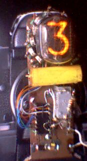 The completed nixie spinner |
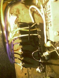 The ten wires leading to
the ten |
 The driver transistors fit
|
Home Page . . . . . . . Email: . . . . . . . . neelandan-at-gmãil·çöm