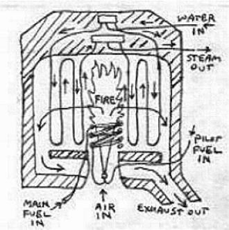
Currently the boiler is an 8-circuit, once-through
("flash boiler") radial-outflow design. It is illustrated in cross-section in my crude, simplified sketch above. Water enters an inlet header at the top of the
boiler, which distributes the water equally into 8 separate specially-designed tube coil assemblies (two are shown in cross-section in the above sketch), each containing
about 150 feet of 1/4 inch outer diameter carbon steel
tubing.
These coils are arranged radially around a
central combustion chamber, and have a combined gas-side
heating area of approximately 75 square feet. As the water passes through these coils, it absorbs heat from the burner gases flowing between the turns of the coils, and by the
time it reaches the end of each coil, the water has turned
into superheated steam at 500 pounds per square inch
pressure and 700� Fahrenheit temperature. The superheated
steam passes from the 8 coils into an outlet header, which
combines the steam flow from the 8 coils into a single
outlet tube of approximately 1/2" inner diameter.
The boiler will measure approximately 18 inches in diameter and 20 inches tall, and will weigh about 100 pounds with the burner fitted.
To heat the steel coils and convert the water pumped
into them into steam, a simple vaporizing burner is located at the bottom of the combustion chamber in the center of
the boiler.
Fuel is pumped at a pressure of 80 pounds per square
inch into a coil of steel tubing exposed to the hot gases
in the combustion chamber. This heats the coil of steel
tubing and turns the fuel pumped through the tube into a
vapor. The fuel vapor, at 80 psi, flows to a ring of
tubing in the center of the air inlet tube, exiting this
ring through 4 or more small holes ("jets") drilled into the top of
the ring. For clarity, only one fuel vapor jet is shown in the above boiler sketch.
The expanding cones of high-speed fuel vapor flowing through the mixing tube from the jets draw
air into the burner, which mixes with the fuel vapor and
burns cleanly in the combustion chamber above the air inlet tube.
Radiant heat from the free flame in the
combustion chamber heats the exposed surfaces of the
surrounding boiler tubes, and the hot combustion gases flow sideways and outward through the gaps between the boiler
tube coils, heating the coils to produce steam. In the above boiler sketch, the horizontal, downcurved arrows moving outward from the fire represent the hot gas flow. The small vertical arrows next to the vertical zig-zag lines representing the tube coil turns, represent the direction of water and steam flow inside the tubes.
The steam produced in the boiler passes through a
spring-closed throttle valve, controlled by a foot pedal ("accelerator pedal") in the passenger compartment. This throttle will be of the
sliding-plate type, and regulates the speed and power of
the car just like the accelerator pedal in an automatic
transmission gas-engined automobile. For safe, instant stops in close maneuvering, the throttle is built to instantly vent all steam from the engine inlet line and cylinders to the feed water heater when the throttle is closed. There is also a linkage to the brake pedal, which positively closes the throttle when the brake pedal is pressed, in the unlikely event of throttle sticking. To help prevent sticking and wear, just before the steam
passes into the throttle a tiny stream of oil is injected
into it, which lubricates the throttle and the engine.
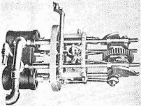
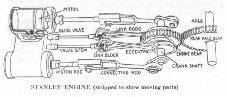
The engine, very similar to the Stanley engine illustrated
above, is a two-cylinder, double-acting,
transverse-mounted, horizontal inline single-expansion steam engine with two inside-admission piston
valves actuated by Stephenson link valve gear, which
controls the inlet and exhausting of steam from both ends
of the cylinders. Cylinder bore is 3.366 inches; piston
stroke is 4 inches. Engine displacement is approximately
142 cubic inches (2.3 liters). Engine weight approximately 80 pounds. The crankshaft has an overhung crank at each end and a central drive gear flanked by the two valve mechanisms. There are 2 main bearings, one directly inboard of each crank.
A Digression On Designing Steam Car Engines
For Smooth And Efficient Running
The two crankshaft throws are phased 90�
apart, giving overlapping inlet and smooth, continuous, controllable torque in low-speed long-cutoff mode. At higher engine/vehicle speeds, the drive wheels and car mass act as inertial "flywheels" to smooth out the torque fluctuations with shorter cutoff. Short cutoff is more efficient, but is undesireable at low speed, because jerky running results from the fluctuations in cylinder pressure and thereby of piston thrust, during piston strokes. Jerky running at low speed/short cutoff is also caused by the Stephenson valve gear's advancing of steam inlet opening ("valve lead", pronounced "leed") and increased exhaust compression at short cutoff. At high speed, however, the increased lead and exhaust compression cushion the pistons, and increase engine life and efficiency.
Also, the flexible engine frame helps smooth out the running of the engine, and the isolation of the engine from the sprung vehicle mass, in the direct-drive designs of Stanleys and other classic steam cars, contributes to the smooth-running driving experience. All these engine design and valve timing factors interact in a complex, subtle, and elegant way. Long cutoff at low speed and short cutoff at high speed, within the time-tested variable valve timing regime of the durable and simple Stephenson valve gear, give a practically ideal combination of smooth, powerful operation and efficient running under all conditions.
It should be noted that smooth running is possible with shorter cutoff at low engine speed, by using more than two cylinders. Unfortunately, this increases the aggregate surface area to volume ratio of the cylinders, resulting in more heat transfer from inlet to exhaust steam via heat absorbing/releasing internal engine surfaces exposed to steam. This heat loss may more than offset the efficiency gains from shorter cutoff, especially with the increased steam/metal exposure times which occur at lower engine speeds. The increased piston area/kinetic mass of multi-cylinder engines also increases engine cost and friction losses, as designers of internal-combustion engines are well aware. Higher engine speeds to reduce steam/metal exposure time may reduce this loss, but results seem to indicate that increased friction losses in high-speed multi-cylinder steam engines outweigh the savings in heat waste. One horsepower worth of extra friction losses will negate 5-10 horsepower worth of heat savings in a light steam powerplant.
Experience with many modern steam car engines patterned after IC engines bears this out. Even with short cutoffs, high expansion ratios, and high exhaust compression, which in theory should more than double engine efficiency, actual fuel efficiency of these designs under typical road conditions tend to be the same as, or worse than, the fuel efficiency of comparable gas cars and 2-cylinder steam cars of the pre-1930 "classic" era, when actual fuel mileage figures are correlated to air and tire drag. It may be possible to do better with high-speed multicylinder steam engines, but it would take considerable investment of labor and R&D funds, and efficiency improvements might be offset by increased production cost and higher amortized development cost.
The thermal and fluid dynamic requirements of steam engines are radically different from those of IC engines; this is why the best results tend to be achieved with steam engines radically different from IC designs.
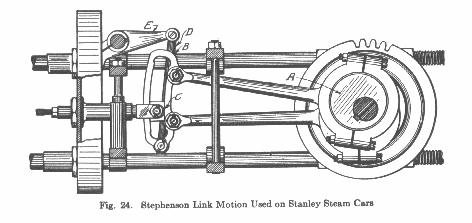
The Stephenson valve gear allows the engine to
be reversed for backing up, and the engine's cutoff in the
forward direction changes automatically from 60% of stroke
admission for smoother running and better control at lower
speeds, to 28% admission for better fuel economy at higher
speeds. Automatic cutoff control is accomplished by incorporating a speed-sensitive kinetic actuator in the engine, similar in principle to the fly-weight governors used on old stationary steam engines.
In steam cars of the pre-1930 era, drivers
have to push a pedal or lever to change the engine cutoff. If they delay or neglect this, their fuel mileage drops off. Automating the cutoff control allows not only easier
driving, but guarantees the best possible fuel efficiency
with this type of engine.
Special small thermostatic inlet and outlet valves in the cylinder heads allow continuous steam flow through the cylinders during engine warmup, and blow out any water that condenses in the cylinders, eliminating the "rocking" procedure used in warming up similar steam car engines of the past, and allowing instant starts. This system is analogous to the automatic "choke" used to facilitate warmup in carbureted gasoline engines. The water pumps will have excess capacity to allow running while warming up this way.
To insure creamy-smooth running, a Stanley-style flexible steel-rod engine frame is planned. Old steam car engines with this type of frame have exhibited rough running when stiffening elements are added, demonstrating the smooth-running value of flexible engine frames. It is possible to design bearings and other components to handle engine frame flex under high load. Flexible engines also weigh less than rigid engines, and are easier to build and cheaper to produce in limited production.
To reduce limited-production cost and unsprung engine weight, advanced fiber-reinforced polymer (plastic) materials are being investigated for all engine parts located in the crankcase. The crankcase of this type of engine is isolated from the cylinders and therefore operates at a low enough temperature to allow use of these materials.
To reduce friction and wear in the engine, ball and roller antifriction bearings are planned for all journals on the crankshaft: connecting rod big ends, main bearings, and valve gear eccentrics. "Classic" steam cars of the pre-1930 era were so equipped; their bearing design was more advanced than today's latest gas and diesel engines.
The engine is built into the center of a non-independent
suspension fiber-reinforced polymer solid rear axle, and drives an aircooled VW
differential via spur gears. There is one spur gear in the
center of the crankshaft, between the two cranks,
and this mates with a spur gear bolted to the spider of the
differential. The drive ratio is fixed at 1:1, so that
with 24" diameter wheels the wheels and engine turn at 840
revolutions per minute at 60 miles per hour.
This very low engine speed eliminates balance, noise, and vibration problems, and also minimizes wear and friction losses (see below). Thus it makes the engine easier to design. Compare this to the 2500 rpm cruising speed of most IC engines, and their 1000 rpm idle and up to 8000 rpm full-power speeds, and remember that speed-related problems increase at the square of engine speed -- eg, twice the speed = 4x the kinetic loads, 3x the speed = 9x the kinetic loads, 4x the speed = 16x the kinetic loads, etc..
There is no clutch or gearshift, and none are needed due to the massive torque capability of this type of steam engine. This engine will be capable of developing more
torque than is needed to spin the tires on dry pavement, so there is no need to gear it down. It can develop this torque at any crankshaft position with the car standing still, so there is no need for a clutch.
This arrangement gives
the highest possible mechanical efficiency, as gearboxes
and clutches in conventional gas cars can waste 6-10% or
more of the horsepower in the form of friction. Friction
losses with this type of direct drive are approximately
2%. Internal engine friction in this low-speed engine dissipates approximately 10% of the energy developed in the cylinders -- much less than the friction losses in high-speed IC & steam engines, which have much greater internal inertial loads.
This arrangement is also mechanically far simpler
and cheaper than conventional multiple drive ratio
transmissions, with their fluid couplings and clutches. Eliminating these complications cuts the cost and increases the reliability of the powerplant.
It is worth noting here that a number of experimental one-off steam cars were built in the mid- to late-20th Century with high-rpm, usually single-acting engines, often idling at stops, and often driving the vehicle through change-speed gearboxes and clutches like a manual-transmission gas car. While better fuel economy has been reported in some of these cars under some constant-speed cruise conditions (importantly, _not_ in typical stop-and-go drive cycles, judging by the data I have seen so far), their road tests raise questions about the durability and overall roadworthiness of high-rpm steam car engines. I have never seen reports of more than a few thousand miles of total road running for these vehicles, which tend to disappear from operation & public view shortly after completion, usually without further reports or explanation.
In contrast, there are hundreds of Stanley steamers, numerous Whites, several Dobles, and many other classic steam cars, some over a century old, which have run hundreds of thousands of miles on their original low-rpm double-acting engines, and which are still running on a regular basis, and which routinely and reliably travel thousands of miles at a stretch on trips and tours. These considerations are part of the reason why I favor a low-rpm steam car engine of generally traditional design -- with considerable improvement and updating.
Today's production gas cars also have engines & transmissions whose basic mechanical design features are not radically new, but are instead greatly improved and updated versions of features used in the early 20th century. Updating and refining features which work (however poorly they may have worked in the early days) has been a very successful design approach in gasoline cars, both technically and commercially, and I plan to try this approach in some aspects of modern steam car design, despite the fact that this approach is, oddly, quite unpopular and controversial among most modern steam car theorists and developers. At one time, I spent considerable time debating these design issues, but now I am working instead to develop & demonstrate my ideas, and (if results are good) to market appropriately-designed equipment directly to the public. A reliable, affordable, and enjoyable automobile speaks for itself.
Steam cars use condensers to recycle the exhaust steam
from the engine into water, which is returned to a water
storage tank to be reused for feeding the boiler. Thus a tankfull of water is recycled many times, and the car can go much further on a water fill-up. I anticipate water mileage of at least 20-30 miles per gallon in my prototype car, or about a 200-300 mile range one one filling of the 10-gallon water tank. I believe this range can be greatly extended with relatively little development work; 100 miles per gallon of water, or more, is within reach.
The Stanley steam car, the most commercially successful and highest-production of the pre-1930s steam cars, uses an
ordinary gas car radiator to condense the steam. This
is possible because of its well-designed feed water heater: a length of the feedwater tube placed in the exhaust steam line between the engine and radiator/condenser. This transfers heat from the engine exhaust steam into the feedwater headed to the boiler. This arrangement increases the fuel mileage and performance of the car by recycling some of the waste heat in the exhaust steam, and at the same time cools the exhaust steam enough that virtually all of it is condensed in a conventional radiator. Water mileage is reportedly 10-14 mpg in these cars, about the same as the fuel mileage. I plan to follow this approach.
Because the engine in the Brow steam car, like the
engines in most classic steam cars, is geared directly to the differential, it does not idle when the car is at rest, such as when stopped at an intersection. This means that
the engine generates no exhaust steam when stopped. When
moving slowly, only a small amount of air flows through the radiator, but at the same time the car is usually using only a small amount of steam. Therefore, no fan is needed to pull air through the radiator, as exhaust steam only needs condensing when the car is moving, and the natural airflow through the radiator at any given speed is roughly proportional to the amount of steam needing condensing.
Under some conditions, however, like
rapid acceleration or slow driving up a steep hill, the
engine produces more steam than the natural air flow
through a reasonable-sized radiator can condense. Under these temporary conditions, a fan or other overload condensing means can be desireable, to give better water
mileage.
(The following section updated 5-29-2000)
Abner Doble claimed that his Doble-Detroit steam car of 1916 would go 1100 miles on a 20 gallon tank of water (55 mpg of water), without a fan, by simply connecting the bottom (outlet) of the radiator to a perforated tube in the bottom of the water tank. Thus, if any excess steam bypassed the radiator due to temporary high loads at low speeds, it would bubble up through the water in the tank, thereby condensing. The water tank in such a system must be designed for good heat rejection. I plan to test a similar approach.
Note that this water mileage was achieved with a car which reportedly got about 8 miles per gallon of fuel. If fuel and water mileage are considered to be roughly proportional, then a car which gets 24 miles per gallon of fuel could get about 165 miles per gallon of water, or 3300 miles on a 20-gallon tank of water, with an equivalent condensing system. This would mean a steam car with water refill intervals equivalent to oil-change intervals in modern gas-engined cars.
I have designed a simple system for recovering the considerable steam (and oil) leakage out of the piston and valve rod seals in the engine. In normal driving, this could allow 3000-mile water tank refill intervals with a much smaller water tank, perhaps a 10-15 gallon tank.
http://www.geocities.com/MotorCity/Shop/3589/