|
|
|
|
|
|
|
|
Switches |
|
The most commonly used discrete inputs are switches, push buttons, such as limit switches. |
|
Introduction
Discrete devices have two states, ON and OFF, while analog devices have or respond an electrical signal varying in value between two end limits.
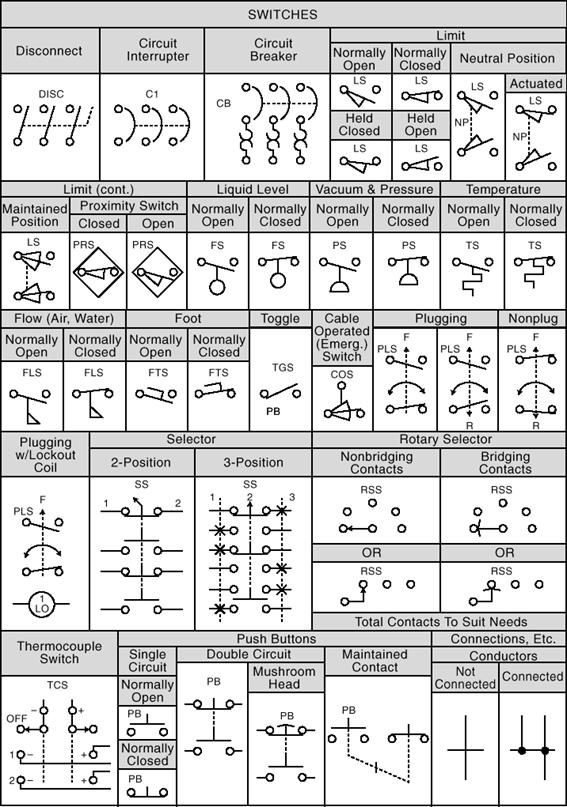
The abbreviation NO stands for normally open: that is, open in the non-actuated position. When actuated, the NO device will close. The abbreviation NC stands for normally closed. When actuated, an NC device goes from the closed position to the open position. Note that for limit switches there are four symbols. Two are straight NO and NC limit switches. The other two are held closed and held open. The designation held closed or held open means that at the start of a process the limit switch is mechanically held in the actuated position, ON or OFF.
Typical discrete-output devices include relays, indicating lights, contactors, and motors. Such devices are ON when power is applied and OFF, or not actuated, when power to them is OFF.
Analog output devices include positioning motors, meters, positioners, and stepper motors. Even though the stepper motor is not strictly continuous (it moves in small steps), it is considered an analog output device.
Switches
PUSH BUTTONS
The push button is an industrialized version of the doorbell button. Push buttons are momentary action devices; as long as they are held down, the circuit remains closed, or open, and it returns to its normal state when the button is released. Push buttons come with NO and NC contacts like relays. For momentary action devices, the normal condition is the inactivated position, just as it comes out of the box. The figure shows the symbols for NO and NC push buttons. Push buttons are relatively modular, consisting of an operator and contact blocks that can be stacked together as required. The difficulty with push buttons used in pre-PLC times is the wiring that had to be done between the relay panel and the push buttons out on the machine. It was common to have hundreds of wires going out to push buttons, and any change in the relay logic often required changing wiring to the push buttons.
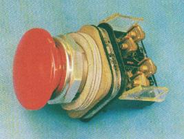
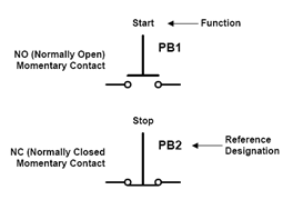
Figure 2-1 Typical Push Button, and Schematic Representation
Reference designation
The reference designation for most push buttons is PB, such as PB1, PB3.
SELECTOR SWITCHES
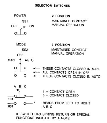
Selector switches are like push buttons except that they remain in whatever position they are moved to. They are also called maintained devices, because they maintain their last position. There is no convention for describing the maintained contacts of selector switches as there is for NO and NC contacts for relays or push buttons. The selector switch symbol has an arrow or truth table to indicate the state of its contacts for each position it can take. The figure shows some symbols for selector switches.
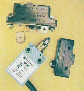
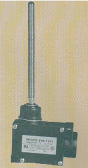
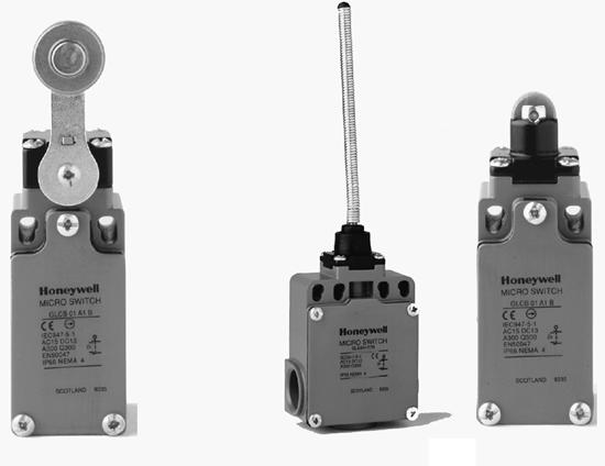
LIMIT (MICRO) SWITCHES
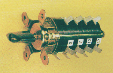
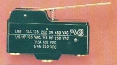
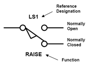
Another common device, the limit switch, is a snap-acting device that is operated by a cam or some other mechanical device. The snap-acting limit switch will change the state of its contact when the operating rod is moved a very small amount from one position to another. Typically, the rod has to move only a few thousandths of an inch to cause the contact to transfer. The figures shows typical units, and the contact representation of a limit switch as well as operating characteristics of a typical switch. Since limit switches are momentary devices, they have NO and NC contacts, as do relays and push buttons.
Limit switches are used in many other sensing devices such as level, flow, pressure, and temperature switches, in which a mechanical sensing system (such as a float, Bourdon tube, or capillary tube) moves a small amount to activate the limit switch. Adjustment are made by moving the limit switch closer or farther away.
Reference designation
The reference designation used for switches is usually S. example S1, S2, etc.
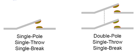
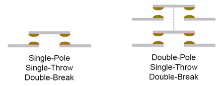
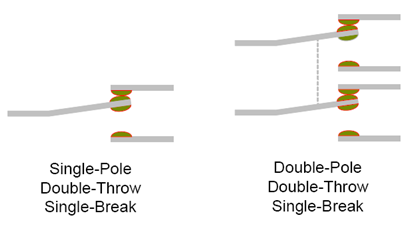
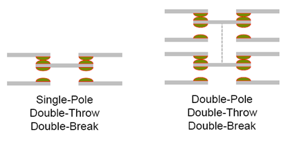
Switch Terminology