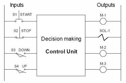
Automated Car Wash
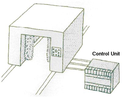
Figure 1-2
The control of the whole process from start to finish can be
automated.
Packing Inspection
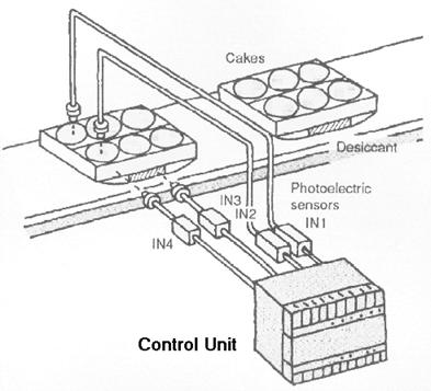
Figure 1-3
Inspect packages to confirm that all required contents are
present.
Cutting Lengths of Metal (Slitter)
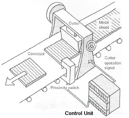
Figure 1-4
Here, a proximity sensor is used to detect when the end of a
metal sheet comes into position and activate a cutter.
Cutting Wire Rods
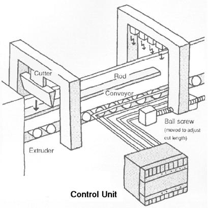
Figure 1-5
Wire rods coming down a conveyor belt are easily and quickly
cut into consistent lengths
Monitoring Personnel Flow
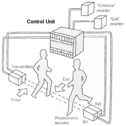
Figure 1-6
Two optical sensors placed at an entrance way can be used to
determine when people enter and exit. Counters can be combined to keep
accurate track of personnel flow.
Controlling Conveyer Movement
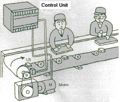
Figure 1-7
Conveyers can be accurately controlled for assembly and
other operations. Timers and limit switches are combined to stop the belt for
a specific time interval and then move it at a set speed for another time
interval
Automatic Fountain Control
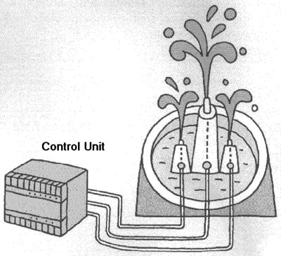
Figure 1-8
Fountains can be controlled using sequential control units
Opening and Closing Garage Doors
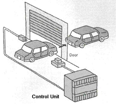
Figure 1-9
A remote control button is used from inside the car to open
the garage door. The rest of the operation, including light control and
closing the door after a set period of time following photoelectric sensor
activation, is automatically controlled.
Batch Control and Automation
A Batch Process is when a number of different operations or
processes (as in process control) are carried out in a specific sequence
according to a formulation or “recipe”.
Typical applications
-
different formulations of a product
eg. paint, pharmaceutical, perfumes, detergent
-
products produced in limited quantities, where dedicated set-ups
would be to expensive
eg. car manufacturing (robotics), and perfumes
-
products that require long maturation times in undisturbed
conditions
eg wine, beer, whiskey …
-
initial processing of chemicals
In any batch control system two things are required
1. a
formulation (recipe) and
2. a sequence
Logical Sequence and Implementation
The logical sequence can be described in the following
manner:
-
flow charts,
-
sequential function charts,
-
state diagrams,
-
timing diagrams.
-
logic diagrams, and
-
ladder diagrams
Ladder diagrams are used extensively in the field of
automation to document a specific implementation of a sequence, and forms part
of the language used to describe the sequence of operations.
Most of these descriptions are to help understand how the
sequence is to progress from step to step. The Ladder Diagram helps in
understanding the sequence, while at the same time documents the actual
electrical circuit.
Most automation is achieved through the use of switches,
sensors, relays, timers, counters, and other components or devices. These
components or devices can be hardwired together to form, what is called a
hardwired control system, or alternatively a Programmable Logic Controller
(PLC) can be used, eliminating the need for hard wiring all these components
and enabling control system changes through the reprogramming of the PLC.
Computers can also be used to effect the control, but are used less frequently
in industrial control applications.
Hard Automation
Machines, which are designed to perform specific functions,
are referred to as hard automation. In these systems, every change in standard
operation demands a change in machine hardware and setup.
Flexible Automation
Machines, which can be easily programmed, or can change over
easily and quickly from one manufacturing setup to another are defined as
flexible automation.
Figure 1-10a shows three fixed mechanical arms along one
side of conveyor.
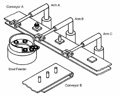
Figure 1-10a Hard Automation
Arm C grips a part taken from the Conveyor B and assembles
it onto the square part. Arm B grips a part taken from the bowl feeder and
assembles it onto the two previously assembled parts. Arm A then transfers the
completed assembly to a special area for temporary storage.
Each of the three arms is limited in its motions: an arm can
go up and down (along axis 1) or back and forth (along axis 2), but no other
motion is possible.
On each of the two axes, only two possible positions exist:
1. Along axis 1, maximum or minimum height.
2. Along axis 2, maximum or minimum extension.
When one of the axes receives a command, it moves until it
is stopped by a mechanical end stop. Any change in the assembly operation
requires a modification in the machine array, or overall arrangement, that may
take considerable retooling and time.
Figure 1-10b shows a single robot replacing all three hard
mechanical arms, to perform a similar operation.
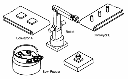
Figure 1-10b Flexible Automation
Changes in the assembly operation performed by an array
including a robot usually require no more than a modification in the
programming.
In other words, flexible automation requires programming or
reprogramming of automated equipment. The next diagram illustrates the
difference. The PLC is the computer of choice in industrial automati