|
Agilent HP 8510A 8510B 8510C 8530A 8530B 8530C acquisition Advantest Agilent Aircraft analyser analyzer Anritsu ANTENNA antennas Aperture Array attack automatic beamshift C130 calibration Com Commercial Comstron CW data dBi design development efficiency Engineering equipment F111 F111 F15 F16 F18 GAIN generator GHz Giga-tronics GPIB HARDWARE Hewlett Hewlett-Packard HP8510 HP8510A HP8510B HP8510C HP8530 HP8530A HP8530B HP8530C HPBASIC HPIB HPVEE HTBASIC IEEE-488 IFR implementation Impulse installation integration International LabVIEW LabWindows/CVI Lock Marconi MHz Microwave Military network Noise Null operator Packard patterns performance Phase Philips Polarisation positioners RACAL radar RADOME RCS RCS receiver RF Rohde scalar Scanning Schwarz Seeker signal SOFTWARE squint STANDARD Swept system SYSTEMS targets Tektronix TEST TFR Tracker training transmission uncertainty vector verification Wiltron
training courses on-site WORLD-WIDE economically !
Impulse Engineering International FAX +61-3 9434 6432 Melbourne Australia
RF / Microwave TRAINING COURSES
Vector NWA Fundamentals
Scalar NWA Fundamentals
Advanced Vector NWA
NEW Installation/Maintenance Analysis
NEW Spectrum Analysis Fundamentals
Prices World Wide
TRAINING BENEFITS
World-Wide on-site presentations using your equipment
Quickly brings staff up to speed revision and/or updating for more experienced staff
Fundamentals and Advanced courses
Provides alignment with industry best practices
Over 10 years experience in international training
Fixed Price
Unlimited number of attendees
Extremely cost effective !
These RF & Microwave network analysis training courses are available be our guest to view and print-off the overviews
TP3301A RF & Microwave VECTOR Network Analysis FUNDAMENTALS Training Course
(For HP8510 HP8720 HP8753 Wiltron 360 Wiltron 37XXX Anritsu MS466X Rohde & Schwarz ZVR and similar
Topics include Vector Network Analysis Basics Vector Network Analyzer Features Vector Measurement Accuracy Issues Time Domain Analysis )
TP3302A RF & Microwave SCALAR Network Analysis FUNDAMENTALS Training Course
(For HP8757 HP8711 Wiltron 562 Wiltron 541XX and similar
Topics include Scalar Network Analysis Basics Scalar Network Analyzer Features Scalar Measurement Accuracy Issues Scalar Analysis Issues)
TP3311A ADVANCED RF & Microwave VECTOR Network Analysis Training Course
(For HP8510 HP8720 HP8753 Wiltron 360 Wiltron 37XXX Anritsu MS466X Rohde & Schwarz ZVR and similar
Topics include Network Analysis Review Advanced Time Domain Non-Insertable Devices Active Device Measurements Analyzer Programming Introduction Antenna Measurement Issues)
TP3303A RF & Microwave PRECISION INSTALLATION & MAINTENANCE Network Analysis Training Course
(For all Wiltron / Anritsu Site Master models including S112 S113 S120A S235A S250A S251A S330A S331A S810A and S818A and other similar analyzers
Topics include Network Analysis Overview Measurement Accuracy Issues including Calibration Fundamentals Distance and Time Domain Fundamentals Analyzer Software Tools and test analysis Basic Power Measurements)
TP3304A RF & Microwave SPECTRUM Analysis FUNDAMENTALS Training Course
(For HP8560 HP8561 HP8562 HP8563 HP8564 HP8565 HP8566 HP8567 HP8568 HP8590 HP8591 HP8592 HP8593 HP8594 HP8595 HP8596E Anritsu MS2601 MS2602 MS2651 MS2653 MS2661 MS2663 and similar
Topics include Network And Spectrum Measurement Principles Basic System Block Diagrams AM & FM Principles Dynamic Range Resolution Bandwidth Noise Levels Low Level Signal Measurements Zero Span and FFT Measurement Accuracy Issues Sources of Error Error Correction (Calibration) Optimal Hardware Configurations and Detection and Display Modes)
HOW TO CONTACT US
Send email to Impulse Engineering International
Melbourne Australia (+61 3) 9434 6432
Impulse Engineering International
55 Maxine Drive
Greensborough VIC 3088
AUSTRALIA
http://au.geocities.com/impulse_eng
TP3301A RF & Microwave VECTOR Network Analysis FUNDAMENTALS Course
TP3301A RF/Microwave Vector Network Analyzer Operator Training Course
Covers RF and Microwave fundamentals as related to vector network analysis
Installs confidence in the use of network analyzers by overcoming the complexities involved in calibration and measurement techniques
advanced applications
Engineers scientists and technicians involved in research development production and/or maintenance who will operate or have operated a vector network analyzer
Advantest R376X
HP 8510 875X 872X 871X
Anritsu MS620J MS3401
Marconi 6210
Wiltron 360 372XX
to increase the productivity of RF/Microwave vector network analyzer operators in measuring devices and to make them aware of limitations in the results obtained
Define network analysis and explain how reflection and transmission measurements are made
Describe the human interface to the network analyzer
Identify sources of error in the measurement hardware
Perform different types of measurement calibration
And where time domain analysis is available
Interpret time domain information
Recognize the effects of masking
Use windowing to enhance time domain information
Apply gating to the time domain information
Use time domain to physically locate responses and faults
NETWORK ANALYSIS BASICS
provides a review of transmission line theory network measurement principles and hardware requirements
Define network measurement terms
Use S-parameters to describe device characteristics
Define the magnitude and phase measurements of linear networks
Identify network analyzer hardware requirements
Name and describe measurement result formats
Determine device operating frequency range by relating reflection and transmission measurements
Interpret measurements derived from phase information such as group delay and electrical length
Describe the basic network analyzer block diagram and data processing flow
Name and describe measurement result formats
provides a review of transmission line theory network measurement principles and hardware requirements
Define the measurements of linear networks
Describe the basic measurement process
NETWORK ANALYZER FEATURES
presents the basic network analyzer features and how to use them in a general measurement sequence
Determine feature accessibility through front panel keys and associated menus
MEASUREMENT ACCURACY ISSUES
provides an overview of measurement errors calibration concepts and measurement result limitations
Describe the systematic errors and error models applicable to reflection and transmission measurements
Perform a frequency response calibration one-port (3-term) calibration and a full two-port (12-term) calibration (where an S-Parameter test set is available)
Identify the most suitable calibration to perform for a measurement
Recognize tradeoffs between network analyzer hardware performance and measurement uncertainty
Identify calibration limitations
Recognize the importance of performing measurement calibration and maintaining calibration standards
provides an overview of measurement errors calibration concepts and measurement result limitations
Perform calibrations for reflection and transmission measurements
Optimize hardware for particular measurement applications
Recognize the importance of performing measurement calibration and using a true open/short calibration standard
TIME DOMAIN ANALYSIS
introduces time domain analysis features (where available)
Describe how time domain information is produced
Interpret time domain displays
Explain the limitations of time domain analysis
Identify the features and differences of the time domain analysis modes
Use gating to isolate device responses
ADVANCED TIME DOMAIN
details the attributes of gating and potential errors introduced into measurement results by them (where available)
Revision of time domain operation
Determine response resolution and alias free range
Identify the regions of displayed results that are effected by incorrectly placed gates
Recognise errors introduced by the incomplete gating out of unwanted responses
Determine the best gate shape to minimise gating errors
TP3302A RF & Microwave SCALAR Network Analysis FUNDAMENTALS Course
TP3302A RF/Microwave Scalar Network Analyzer Operator Training Course
(includes spectrum analyzer/tracking generator systems SPEC AN/TG)
Covers RF and Microwave fundamentals as related to scalar network analysis
Installs confidence in the use of network analyzers by overcoming the complexities involved in scalar network analyzer specific problems calibration and measurement techniques
HP 875X 871X 859Xopt010 856X/85640A 71XXX/703XX
Marconi 62XX
Advantest TR4623 R3X61
Wavetek 8003 1175
Wiltron 562 5400 541XX
to increase the productivity of RF/Microwave scalar network analyzer or spectrum analyzer/tracking generator system operators in measuring devices and to make them aware of limitations in the results obtained
Define network analysis and explain how reflection and transmission measurements are made
Describe the human interface to the network analyzer
Identify sources of error in the measurement hardware
Perform different types of measurement calibration
Change measurement hardware to improve measurement accuracy
Identify measurement issues in scalar signal detection schemes
SCALAR ANALYSIS ISSUES
presents specific scalar analysis features and concerns
Describe measurement trade-offs between narrow- and broad-band detection schemes where spurious levels sweep speed and dynamic range issues exist
Understand when either AC or DC detection mode is preferred (where available)
TP3311A ADVANCED RF & Microwave VECTOR Network Analysis Course
TP3311A Advanced RF/Microwave Vector Network Analyzer Operator Training Course
Specific measurements and applications in vector network analysis which have a higher level of difficulty are covered
Vector network analyzer programming is also included for data acquisition and/or automation
to expand the capability of RF/Microwave vector network analyzer operators to include complex devices that require detailed knowledge of network analyzer operation
Review network analysis principles
Calibrate for and measure non-insertable devices
Configure and calibrate for active devices with attention to signal levels
Develop modular software programs for automating measurements
Measure antennas with receiver style configurations
Determine response resolution and alias free range
Recognise and minimise gating errors
NETWORK ANALYSIS REVIEW
provides a review of network analysis principles
Revision of network measurement terms S-paramaters and network analyzer hardware requirements
NON-INSERTABLE DEVICES
presents techniques for devices that force the measurement configuration to be different from the calibration configuration
Understand what a non-insertable device is
Describe the preferred calibration techniques for non-insertable devices
ACTIVE DEVICE MEASUREMENTS
discusses the measurement of devices having various combinations of gain and sensitivity
Understand active device measurements including small signal gain and gain compression
Describe the necessary precautions taken to give protection against damage from high power levels
Determine the appropriate configuration to cater for signal levels during both calibration and measurement
Identify the most suitable calibration to perform for a measurement
ANALYZER PROGRAMMING INTRODUCTION
provides a simple approach to creating automated measurements that will assist in more data acquisition intensive applications
Understand the use of program variables
Utilise human interfacing with softkeys
ANTENNA MEASUREMENT ISSUES
details the hardware and software requirements for measuring antennas
Utilise input definitions for receiver style measurements
Understand the trade-offs between configurations using standard test-set hardware and external mixing
Use automated data extraction techniques and test for acceptable antenna positioner angular velocity
TP3303A RF & Microwave PRECISION INSTALLATION & MAINTENANCE Network Analysis Training Course
TP3303A RF/Microwave Precision Installation & Maintenance Network Analyzer Operator Training Course (for Anritsu / Wiltron Site Masters and similar)
Covers RF and Microwave basics as related to vector and scalar network analysis
Installs confidence in the use of economy precision reflection transmission and distance to fault instruments by overcoming the complexities involved in calibration and measurement techniques
RF/Microwave installation & maintenance network analyzers for example Anritsu / Wiltron Site Masters
S112 S330A
with built-in distance-to-fault (DTF)
S113 S331A S810A S818A
with built-in (DTF) & 2-Port Test
S120A S235A S250A S251A
to increase the productivity of RF/Microwave Installation & Maintenance Network Analyzer operators in measuring transmission lines (cables) and other devices and to allow them to further interpret the results obtained
Define network analysis and explain how reflection and transmission measurements are made
Describe the human interface to the network analyzer
Identify sources of error in the measurement hardware
Perform different types of measurement calibrations and configure for improved measurement accuracy
And using software and/or directly on analyzers which have distance to fault analysis
Use distance domain to physically locate responses and faults
Recognize the difference between distance to fault displays and traditional time domain analysis
Use windowing to enhance distance to fault information
Interpret distance to fault information
DISTANCE TO FAULT ANALYSIS
introduces distance to fault analysis features (using analyzer software tools and/or directly on analyzers which have distance to fault analysis functions)
Describe how distance to fault information is produced
Interpret distance domain display traces
Explain the limitations of distance to fault analysis
Determine response resolution and alias free range
Use calibrated mismatches to eliminate phantom faults in distance to fault traces of cable or waveguide lengths while clearly identifying full lengths
Select appropriate attenuation and relative propagation velocity factors
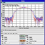
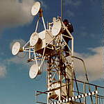
ANTENNA / RCS TEST SYSTEMS
Antenna RCS Measurement Window
ANTENNA / RCS TEST SOFTWARE & HARDWARE
Our antenna / RCS test system expertise
Test patterns for all types of antennas and RCS targets
Application and test facility tailored software packages capable of driving commercial and home made positioners
Cost effective upgrades or completely new systems
Antenna / RCS range facilities supported worldwide
Full antenna / RCS test system data acquisition and control activities including design hardware/software development installation/implementation integration verification documentation and operator training
Modern test system architectures using PC hardware and RF/Microwave signal generators alternatives
Specialist in HP/Agilent 8510 and 8530 receivers
Options to economise through the selection of re-furbished used automatic test equipment (near new)
Feasibility and viability studies
Fixed Price or labour & materials based contracts
testing procedures antenna / RCS range configurations operator entered information parts lists cable routing schematic diagrams antenna alignment issues system performance uncertainties software installation instructions antenna test parameters manual operation mode overrides
ANTENNA / RCS TEST SOFTWARE FUNCTIONS & FEATURES
Generic and batch measurement windows
Automatic test sequences and segments determined from test range feeder bands (such as waveguide) multiple RF/MW sources & frequency ranges and sweep types (such as CW step and ramp modes)
Positioner azimuth elevation and rotation axes
Positioner attributes supported (such as acceleration profile threshold)
Any specified data file structure
Spreadsheet format (tab delimited) files in a device/date/config/polarisation/scan_axis directory tree structure is recommended
Microsoft Windows3.1 95 98 2000 XP NT
HPBASIC for HP9000/300 Workstation series
HPBASIC for Microsoft DOS on HPBASIC Language Processor Card
HP Instrument Basic for Microsoft Windows
ANTENNA / RCS MEASUREMENT Window For simple single frequency testing
(Scan Boresight)
Scan (Angle) Resolution Margin (for acceleration)
Aperture PLOT Measurement monitoring and warnings to prevent invalid (skewed) data
Test Frequencies CW or Swept frequencies (Ramp or Step modes) CW START STOP
Sweep Characteristics Number of Trace Points Sweep/Dwell Time Quick Step Fast Lock Speed
Parameter Definition Phase Locking (to) Numerator Denominator (all ratios are covered)
Dynamic Range Averaging Resolution Bandwidth Source Power Plot Scales
RF/MW SOURCE CONFIGURATION Window Define Source Name source Start and Stop frequency range Sweep CW/Ramp/Step (capability) EIP Lock (to counter) ALC Internal/External/mmModule Harmonic (for mmModule)
RF/MW BAND CONFIGURATION Window Define Band Name band Start and Stop frequency range
IEEE-488 Window Define IEEE-488 Addresses for receiver sources test sets EIP Counter Positioner Controller
POSITIONER MODE Window Scanning/Manouvering/Boresight control parameters including Acceleration Low Drive Profile Speed Speed Range Threshold
POSITIONER Window Define (user selectable) Boresight and User frequented angles
RCS REFERENCE Window Type Sphere/Triangular Trihedral/Flat Square Plate Radius/Main Dimension RCS Calculator
FILE SAVE Window Test Particulars (user entries) stored with measurement data are Model# Serial# Manufacturer Notes Configuration Notes Test Type Range Polarisation Device Axes (Degrees)
TEST EXECUTIVE Window For multiple frequency & comprehensive testing Captures all of the above features for batch measurements which includes automatic handling of band crossings (both RF/MW source and range waveguide) measure Antenna Pattern RCS background Cal RCS Target
DISPLAY Window plot area X and Y axis Label Units Max Min Text1 Text2
DISPLAY DATA TYPE Window load Device data apply Antenna Gain file apply RCS Reference data apply RCS Background correction Normalise
STANDARD GAIN Files Frequency (MHz) and Factor (dBi) data
Test Executive Window
running multi-frequency banded
multi-configured antenna ranges
normalisation background corrections
Antenna / RCS Test Software and Hardware
TP3304A RF & Microwave SPECTRUM Analysis FUNDAMENTALS Training Course
HP8560 HP8561 HP8562 HP8563 HP8564 HP8565 HP8566 HP8567 HP8568 HP8590 HP8591 HP8592 HP8593 HP8594 HP8595 HP8596E Anritsu MS2601 MS2602 MS2651 MS2653 MS2661 MS2663 and similar
Topics include Network And Spectrum Measurement Principles Basic System Block Diagrams AM & FM Principles Dynamic Range Resolution Bandwidth Noise Levels Low Level Signal Measurements Zero Span and FFT Measurement Accuracy Issues Sources of Error Error Correction (Calibration) Optimal Hardware Configurations and Detection and Display Modes)
RADOME TEST SYSTEMS
Radome Positioner
F111 TFR Antenna & Radome
Radome Test Software and Hardware
Positioner Arm & F111 Radome
F111 Attack Antenna
Null Seeker/Tracker Array
F111 Transmission/Beamshift
F111 Calibration/Status
RADOME TEST SOFTWARE & HARDWARE
Test patterns for all types of antennas and RCS targets
Radome testing of all types including Military and Commercial Aircraft such as C130 F15 F16 F18 F111 737 747 757 767 777 A340 A360 A380
Cost effective upgrades or completely new systems
Application and test facility tailored software packages which include special diagnostics modes and embedded off-line operator training test runs that conveniently review all aspects of the radome testing (test range calibration radome parameters)
Full radome test system data acquisition and control activities including design hardware/software development installation/implementation integration verification documentation and operator training
Options to economise through the selection of re-furbished used automatic test equipment (near new)
Modern test system architectures using PC hardware and RF/Microwave signal generators alternatives
Specialist in HP8510 and HP8530 receivers
(Impulse Engineering was Hewlett-Packard's consultant and software/hardware developer for the Air Force's F111 and F18 Nose Radome Test System)
Feasibility and viability studies
Fixed Price or labour & materials based contracts
Radome range facilities supported worldwide
testing procedures radome range configurations operator entered information parts lists cable routing schematic diagrams antenna alignment issues system performance uncertainties software installation instructions radome test parameters manual operation mode overrides
Positioner Arm & F111 Radome
F111 Attack Antenna
Null Seeker/Tracker Array
F111 Radome Test Software
transmission efficiency & beamshift
tests for attack radar position(s) and window for range
specific calibrations
reference level calibration (red-line levels and beamshift positions)
special functions and status report window
ATE SYSTEM SOFTWARE & HARDWARE
Our test and measurement system expertise will provide you with the following
Anritsu HP Hewlett-Packard Agilent Wiltron Rohde & Schwarz Marconi Advantest Tektronix Giga-tronics Comstron IFR Noise Com Philips RACAL
Application and test facility tailored software packages which include special diagnostics modes and embedded off-line operator training test runs that conveniently review all aspects of the radome testing (test range calibration radome parameters)
Full automatic test system data acquisition and control activities including design hardware/software development installation/implementation integration verification documentation and operator training
Options to economise through the selection of re-furbished used automatic test equipment (near new)
Modern test system architectures using PC hardware with data acquisition cards
Cost effective upgrades or completely new systems
Feasibility and viability studies
Fixed Price or labour & materials based contracts
testing procedures radome range configurations operator entered information parts lists cable routing schematic diagrams antenna alignment issues system performance uncertainties software installation instructions radome test parameters manual operation mode overrides
HPBASIC ported to HP Instrument Basic for Windows and conversions to HPVEE LabWindows/CVI and LabVIEW
Automatic Test Equipment Systems
ATE System Software Hardware
RF & MICROWAVE SPECTRUM ANALYSIS
TP3304A RF & Microwave Spectrum Analyzer Operator Training Course
Covers RF and Microwave fundamentals as related to spectrum analysis and network analysis (requires tracking generator)
Installs confidence in the use of spectrum analyzers by overcoming the complexities involved in the use of key features and measurement techniques
Provides a basis for advanced applications
HP/Agilent 856X 859X 70XXX
Anritsu MS260X MS265X MS266X and many more
"The Training Guarantee Your Questions Answered" Australian Taxation Office 1 July 1992)
to expand the capability of RF/Microwave spectrum analyzer operators to include complex devices that require detailed knowledge of network analyzer operation
Measure signal levels and frequencies accurately
Determine signal modulation types
Improve the displayed test signal dynamic range to find low level signals such as spurs and low power transmitters
Analyze signals further with key features such as zero span and FFT modes
Use a spectrum analyzer as a network analyzer and characterise components accurately
Review network analysis principles
Understand the basic scalar calibration techniques for return loss and insertion loss measurements
SPECTRUM MEASUREMENTS SIGNAL ANALYSIS
provides a coverage of analyzer configurations which assist in identifying and characterising signals
Resolve signals
Extract signals from noise by understanding detector modes attenuation setting and video averaging
Locate where in the analyzer hardware that operator settings cause changes
Determine simple amplitude modulation depth frequency modulation deviation and modulation rates using traditional zero span and FFT techniques (where available)
SPECTRUM ANALYZER FEATURES
presents the basic spectrum analyzer features and how to use them in a general measurement sequence
Determine feature accessibility through front panel keys and associated menus
COMPONENT MEASUREMENTS (Tracking Generator Required in Spec An)
MEASUREMENT ACCURACY & SCALAR ANALYSIS ISSUES
presents specific scalar analysis features and concerns and provides an overview of measurement errors calibration concepts and measurement limitations
Describe the systematic errors and error models applicable to reflection and transmission measurements then optimize hardware for particular measurement applications
Perform calibrations for reflection and transmission measurements and recognize the importance of performing calibrations with true standards
Recognize tradeoffs between analyzer hardware performance and measurement uncertainty and identify calibration limitations
Describe measurement trade-offs between narrow- and broad-band detection schemes where spurious levels sweep speed and dynamic range issues exist
Understand when either AC or DC detection mode is preferred (where available)
designed and developed by Mr Glenn Williams (B.Eng) of Impulse Engineering
Glenn has designed developed and instructed RF & microwave test equipment usage programs since 1985 including many as an RF/Microwave Engineer for Hewlett-Packard over an 8 year period
Glenn has completed numerous train the trainer and presentation type courses
Some of the organisations to benefit from Glenn's expertise during training programs are
Aerospace Technologies of Australia (ASTA-formely GAF Govt
Aircraft Factory)
ADI Electronics (St Marys NSW)
ADI Marine (Garden Island NSW)
Box Hill TAFE (Melbourne)
Communications & Energy Corp (Syracuse NY)
Civil Aviation Authority (Canberra)
CSIRO Department of Radiophysics (NSW)
CSIRO Department of Applied Physics (NSW)
Defence Science and Technology Organisation
Microwave Radar Division (Adelaide)
Electronic Warfare Division (Adelaide)
Materials Research Laboratories (Melbourne)
Department of Defence (Army Navy Air Force)
Mobile Operational Technical Unit
(MOTU Garden Island NSW)
Directorate of Naval Communications Eng
RANTEWSS
RAEME Signals
Defence Signals Directorate
RAAF Base Calibration Centres
Department of Transport and Communications (Canberra)
Fairey Australia Ltd (Adelaide)
Hong Kong National Standards Laboratory
Jenkins Engineering (Sydney)
J.N.S
Electronics (Australia) Pty Ltd (Melbourne)
Mitec Australia Ltd (Brisbane)
Mt Newman Mining (for AWA in Port Hedland WA)
NEC Australia Pty Ltd (Melbourne)
NSW Police Joint Tactical Services Group (Sydney)
NSW Police Digital Voice Privacy Section (Sydney)
OTC Australia (Sydney)
Quiktrak Technologies Pty Ltd (Adelaide)
RFS Radio Frequency Systems Pty Ltd (Adelaide)
RFS Cablewave Div (Nth Haven CT)
Spinaway Cables (National Cables Sydney)
Telstra Electronic Products & Services (Melb Brisbane)
Telstra Research Laboratories (Melbourne)
Tidbinbilla Space Tracking Station (Canberra)
Transfield AMECON Ltd (Melbourne)
Universities of Melbourne Sydney Adelaide Queensland and Auckland
BAE SYSTEMS
Asia Japan Yen Korea Taiwan Asia South East South Pacific Fiji Hong Kong Indonesia Malaysia New Guinea New Caledonia Philippines Samoa Singapore Thailand Vietnam Australia Adelaide Brisbane Canberra Darwin Hobart Melbourne Perth Sydney Canada Calgary Edmonton Montreal Ottawa Toronto Vancouver Winnipeg China Pei-Ching Shanghai Shenyang Tsingtao Europe Austria Euro Belgium Bulgaria France Germany Greece Ireland Italy Luxembourg Netherlands Poland Portugal Spain Switzerland Greenland Frederikshaab Godthab Iceland Reykjavik Burma India Pakistan Sri Lanka Middle East Iran Kuwait Saudi Arabia Turkey United Arab Emirates New Zealand Auckland Christchurch Hamilton Wellington Russia Leningrad Moscow Scandinavia Denmark Finland Norway Sweden South Africa Cape Town Durban Johannesburg Port Elizabeth United Kingdom Birmingham Sterling Edinburgh Glasgow Liverpool London Manchester USA Alaska Hawaii
Agilent Training & Events: PNA Series Microwave Network AnalyzersAgilent Training & Events: RF & MicrowaveRFDesign.infoRf/Microwave Lightwave Engineering LaboratoryRF Cafe Network Analyzers Test Equipment & Calibration (newBesser Associates Courses for RF Wireless Measurements TrainingRF Microwave Lab RulesSatellite & Network Communications Russ Pittman, Consultant ResumeAgilent Overview: PNA Series Microwave Network AnalyzersSorokasoft Training ServicesAgilent (HP) 8720A Network Analyzers RF Vector NetworkAgilent (HP) 8720B Network Analyzers RF Vector NetworkManufacturers RF Microwave telecommunication laboratorySNA Scalar Network Analyzer (20 GHz 40 GHz 50 GHz 110 GHzMicrowave Measurement Training Course PresentersR. A. Wood Associates Engineering Consulting, RF MicrowaveDEPARTMENT ELECTRICAL COMPUTER ENGINEERINGMicrowave Vector Network AnalyzersAerospace Consulting -- wireless, rf, rf design, wireless designEuropean Microwave Week 2004 AmsterdamLEONARDO DA VINCI PILOT PROJECTS QUESTIONNAIRE FOR TEACHERSDigital Oscilloscopes, Power Supplies, Spectrum Analyzers, NetworkProgress Report Rf Microwave Metrology PTBLARGE-SIGNAL NETWORK ANALYZER TECHNOLOGY Preliminary Product OverviewVNA Microwave Vector Network Analyzer 37100C 37200C 37300CEmbedded Local Oscillator Measurement Capability Sets New StandardMicrowave Measurements Microwave Encyclopedia Microwaves101.comANTENNA GAIN MEASUREMENT WITH MODULAR ANECHOIC CHAMBER KITWelcome Amitec Electronics Ltd.Laboratory for microwave microelectronic measurement modeling (4M)Radio frequency & Microwave MetersARTIFICIAL NEURAL NETWORK MODELING FOR IMPROVED ON-WAFER LINEAgilent Training & Events: RF & MicrowaveAgilent Training & Events: E4448A PSA Series Spectrum AnalyzerIH99600 Protek 3201N RF Spectrum AnalyzerKeithley Instruments Inc. RF Microwave ProductsRFDesign.infoElectrical Engineering Metrology/Measurement RF MicrowaveElectrical Engineering Metrology/Measurement Basic RFEconomy Microwave Spectrum AnalyzersRF Microwave Lab RulesUsed Hewlett Packard Models 8590D/E Spectrum Analyzer SeriesRF spectrum & network analysers Measurement InnovationManufacturers RF Microwave in India,Wireless & MobileSorokasoft Training ServicesR. A. Wood Associates Engineering Consulting, RF MicrowaveUnderstanding RF & Microwave Specifications Part I- DeveloperNFL Awards Anritsu Spectrum Analyzer Contract ReutersBesser Associates Courses for RF Wireless Measurements TrainingMicrowave Measurement Training Course PresentersEuropean Microwave Week 2005 ParisRF & Microwave Circuit Design Laboratory WWW pageMicrowave Active Circuit Design Training System: MT-10600Radio frequency & Microwave MetersCompactPCI-Systems.com test equipment rf Products for EmbeddedDEPARTMENT ELECTRICAL COMPUTER ENGINEERINGTest & Measurement: signal analysis, test solutions, measureAerospace Consulting -- wireless, rf, rf design, wireless designRF Infrastructure & Applications, Microwave Radio TESSCO 800Pms Seminar: RF Microwave ReceiversRF (Wireless) Fundamentals 1- Day SeminarDigital Oscilloscopes, Power Supplies, Spectrum Analyzers, NetworkConnect802 Corporation Turnkey Wi-Fi Wireless NetworkingTSCM Training from REIAeroflex Incorporated: Home PageT /F DAgilent Search Results: Training & Application EngineeringAgilent's 8510 Network Analyzer Transition PNA Engineering ServiceMicrowave Encyclopedia MicroWaves101.comMARCH Microwave Systems B.V.Trade-in your 8510 or 8530 for PNAApparatus method for microwave imaging excavationConnector Reference listThird Millennium Engineering: PrincipalTIS Address Search ResultAgilent PN 8510-14 Using Multiple Test Sets with Agilent 8510C20 Years InnovationMEASUREMENT COMPUTATIONAgilent Network Analyzer Selection GuideTELEMETRY SYSTEM PART 1 GENERAL 1.01 SCOPE WORK A) Perform allDesign Optimization Microwave Circuits Systems UsingetricSpace research 164x240III-Vs ReviewN94-30550Executive Interview: Greg Maury, President & CEO, Maury MicrowaveCascade Microtech, Inc.:RF Calibration & WinCal FAQCascade Microtech, Inc.:Engineering Products DivisionIMPULSE ENGINEERING INTERNATIONAL HOME PAGEConnector Reference listMICROWAVE MICROMACHINED CAVITY FILTERSESD protected SiGe HBT RFIC Power AmplifiersBestimmung der Zusammensetzung von Lebensmitteln mit künstlichen033095-1-F High Efficiency Micromachined Antennas: MicromachinedAfdeling for KommunikationsteknologiRfdude.com LLCIMPULSE ENGINEERING INTERNATIONAL HOME PAGECommScope ::: Andrew ::: Partners Services/Andrew Systems IncOhio State UniversityHam Radio Technical ReferenceDesigning with TRF6900 Single-Chip RF Transceiver (Rev. E)微波技术网- Powered by Discuz! BoardABET Engineering Criteria Self-Study Report for Bachelor微波技术网FTP资源汇总---不断更新中- FTP专区- 微波技术网论坛iTownRL-965 Millimeter-Wave Polarimetric Radar System as an Advanced微波技术网FTP资源汇总---不断更新中- FTP专区- 微波技术网论坛iTownSpaceNow * Education. Arguments. Ideas.phorum Fragen zur Kommunalpolitik direct loan onlineRadio-frequency connector interconnect reliability in ... Analysis a novel expanded tip wire (ETW) antenna for microwave ... IEEE Antennas Propagation Magazine A novel course microwave monolithic integrated circuit (MMIC ... A Novel Course Microwave Monolithic Integrated Circuit Design ... A Multipronged Approach Electronic Packaging Education ... Modeling Sensitivity Analysis Circuit Parameters for Flip ... Welcome IEEE Xplore 2.0: MMIC's for an integrated RF spectrum ... Millimeter Wave RF Front End Design using Neuro-Genetic Algorithms OCRed document An Automatic Test System for Axial Ratio GPS Microstrip Antenna, Welcome IEEE Xplore 2.0: AUTOTESTCON 2003. IEEE Systems ... ATE technology trends AUTOTESTCON '93. IEEE Systems Readiness ..Final Report NAGW-2151 RETRIEVAL SOIL MOISTURE ROUGHNESSSite Master™ Microwave Transmission Line Antenna AnalyzerSite Master™ Cable Antenna Analyzer S331D AnritsuBroadband Site Master™ Microwave Transmission Line AntennaSite Master™ Cable Antenna Analyzer 2 MHz 1600 MHz S113CAndrew Corporation Expands Popular Wireless Training CourseSite Master™ Cable Antenna Analyzer [ 2MHz 1600 MHz] (S113CSite Master Site MasterAnritsu SiteMaster TrainingSite Master™ Cable Antenna Analyzer 2 MHz 1600 MHz S312DWelcome ETECSA [services page]Welcome ETECSA [home page]Fundamental VSWR training program includes practical demonstrationsTest EquipmentTalley Com |Online Store Anritsu Site Master FormAnritsu NordicAdtest Advanced Test Measurement SolutionsRF, Microwave, Wireless, Data Communications Optical TestNext Generation ltd Telecommunications rigging servicesReliance :: Bharti :: Tata :: Ericsson :: Nokia-SiemensAnritsu Site Master CourseWorkshopsTest & Measurement: signal analysis, test solutions, measureRF Infrastructure & Applications TESSCO.comSite Master Site MasterAnritsu SpainAnritsu Italy Contact UsMUTI Safety TrainingAnritsu RF MarketingWireless Design Online: Digital Marketplace for communicationsSite Master S331D/S332DAndrew's Node-C RF EnhancerTOSHNIWAL ENTERPRISES CONTROLS PRIVATE LIMITEDAntenna Systems Technology Magazine ConferenceWireless Developer NetworkAnritsu Belgium Contact UsUS INSTRUMENT SERVICES Test Equipment Rental, Sales ServiceVLSI DesigningRoos Instruments, Inc.RI Product Details (RI7100A)Agilent Overview: Aerospace & Defense ATE Systems ServicesAgilent Overview: Aerospace & Defense ATE Systems ServicesRF Microwave Engineering SitesATE System Speeds Avionics TestingMICROWAVES & RF MILITARY ELECTRONICS NOVEMBER 2007 ISSUERF Cafe Technical Services Consulting, Training RF Microwave Devices ThomasNet.comTeradyne Products Catalyst NewsProducts & ServicesIsrael Aerospace Industries Ltd.Giga systems Ltd RF Microwave Products designTest Solutions Test SolutionsRF/Microwave Signal Generator MG3690B Series AnritsuTrango Broadband Wireless Presents Licensed Microwave BackhaulInterfax Systems: Integration Services Partner'sAutomatic Test Equipment (ATE) for Functional Tests US (United2520GTA RF/Microwave Signal GeneratorRF MEMS Switches Deliver Early PromiseVicom Leading way in Test MeasurementDirectory Federal Laboratory Technology Resources: A Guide ... Google Books ResultTestimonials from Industry Experts- Developer Zone NationalAWR's Microwave Office Design Suite Selected by Eagle Test SystemsIntegrators for QuadTech's Electrical Safety Passive ComponentTest Measurement .com buyer's guide providing productsMicrosoft PowerPoint 0440 Richard Beers.ppt2400 Series Family Datasheet microwave synthesizer GigaKeithley Instruments Inc. Switching ControlAgilent Technologies Europe web site, latest news contact detailsSage Laboratories, Inc. Company ProfileChannel Partners & Solution ProvidersRA Mayes EMC, RF, Microwave Environmental Test SystemsETS-Lindgren EMC RF Microwave Testing, Measurement Shielding, General Purpose Antenna Test LabsMicrowave Antennas, Horn Antennas, Antenna Positioners, Microwavemicrowave, RF circuit design, antenna designTest Antenna GlobalSpecAntenna Systems Technology Magazine ConferenceAntenna Systems Technology Magazine ConferenceKeithley Instruments Inc. RF Microwave ProductsAR RF Microwave Instrumentation Modular RF Receiver SystemsRF Globalnet: Digital Marketplace for RF/microwave,Microwave Horn AntennasITEM: Practical considerations in upgrading RF immunity testSimulation Software aids RFmicrowave antenna designRF Microwave Design Tutorials RF DesignLine How-ToMobile/Cellular Technology Aeroflex Test MeasurementAerospace Consulting -- wireless, rf, rf design, wireless designAR Worldwide RF/Microwave Instrumentation (Compliance EngineeringEMC, RF & Microwave Test Solutions Components SystemsMicrowave Engineering Online GPS RF antenna modules for mobileANTENNA RF MICROWAVE TESTINGRF/Microwave Antennas Information Business.comRF Microwave Components SolutionsRF test fixture for adaptive-antenna radio systems Patent 6023203Test & Measurement Equipment antennas Information ZoomInfoHomebrew RF Test Equipment SoftwareRF Microwave Engineering SitesDiarcy Technologies -- Consumer Commercial CapabilitiesBroadband Site Master™ Microwave Transmission Line AntennaPractical RF Microwave Design Oxford University Department for23042_RadomeP1.ai 8/19/05 9:14:30 AM 23042_RadomeP1.ai 8/19/05 9RF Cafe Engineering Calculators & Converter Applet WebsitesAEMI 261 RF Absorber Material for EMC, Witeless, AutomotiveRamayes.com R A MayesRF/Microwave Electronics AllBusiness.com Business DirectoryWide range test systems available from FaradayGoogle Groups results for rf microwave antenna test systems software23042_RadomeP1.ai 8/19/05 9:14:30 AM 23042_RadomeP1.ai 8/19/05 9Antenna Systems Technology Magazine ConferenceAntenna Systems Technology Magazine ConferenceNew Radome Enclosure Enhances Antenna Usage| ETS-Lindgrenhttp://www.orbitfr.com/Index.asp?ItemID=261ORBIT/FR Commercial Aviation Radome Test FacilityTest Antenna GlobalSpecEuropean Microwave Week 2006 ManchesterT /F DComplex Antenna System DesignRF Cafe Antenna WebsitesITGlobe-Exclusive Authorized VendorsSea-Port Technical Sales, Northwest RF/Microwave Manufacturer'sOpen Directory Business: Telecommunications: Equipment: TestingRF Microwave Devices ThomasNet.comSlide 1Feedback control system for radomes Patent 7088308Microwave ComponentsIntroduction RF StealthCSIRO ICT CentreAntenna Range Design Howland CompanyAir, Land Sea Platforms Q-par AngusRF AssociatesGoogle Directory Business > Telecommunications > Equipment > TestingSpace Careers Space Industry Directory Ground SystemsLatest Electromagnetic Simulation Continues TransformArchitecture for RF signal automatic test equipment US PatentOrbitfr.com Orbit Frhttp://www.vermont-rep.com/vermont/line.htmlRadome Structural Analysis2002 IEEE MTT-S Exhibition Guide. (O-S). Industry & BusinessENTERPRISE MICROWAVE RADIO: Planning a Radio NetworkMIT Radiation Laboratory Series: 28 Volumes CD RomARMMS :: RF & Microwave Society Conferences2008 Navy Opportunity Forum®Military & Aerospace Electronics Articles, November 2006
|