 =100 meters
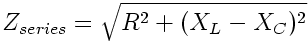
| The key here is represented in the formula for impedence, mismatches of which will cause standing waves: | |
| Given that capacative reactance ( | 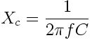 |
) | and inductive reactance ( | 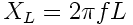 |
) are both frequency sensitive (f), different frequencies are going |
| to result in different impedances at the antenna, resulting in an impedance mismatch if not compensated for. Hence, the use of an antenna coupler in the ARC-190 system. |
 |
RT-1341 - The receiver/transmitter modulates audio into RF and vice versa. It
is notable that there are two IF frequencies, 97.8 and 1.8 MHz. This leads to one of
the key features of the system: dual conversion; simply meaning that the R/T uses
two stages of heterodyning. Remember now, that when you mix a signal, you get 4 signals: 2 original, 1 sum and 1 difference. The highest quality signal lies in the difference signal, so the HF system uses it. However, using the difference signal can increase the occurence of unwanted and interfering image signals. To reduce this interference, the R/T simply employs a second stage of coversion or hetrodyning. Another key feature of the R/T is its use of frequency synthesizers. Many radios use a VCO (Voltage-Controlled Oscillator) because it is a simple and effective way of producing a large number of frequencies, but the drawback of these oscillators is that output frequencies are not as highly accurate as those in crystal oscillators. And while the crystal oscillator is highly stable, it can only produce one freqency which would seem to make it unsuitable for a system like the ARC-190 which has 30,000 channels. So to maintain a high degree of accuracy and a wide selection of frequencies, the system uses a frequency synthesizer which is basically a bank of crystal oscillators, the outputs of which are mixed to form the desired frequency. |
|
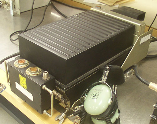
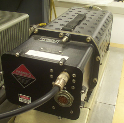
CU-2275 coupler - The HF coupler provides the impedance matching necessary for
transmission on such a wide range of low frequencies. When keying on a new
frequency, you can hear the 'tune tone' on your headsets. During this duration,
the R/T generates a 100 watt signal which is used by the coupler to electrically
tune the antenna to match the input impedance. Note that the coupler is pressurized to 7±1 PSI with dry nitrogen (air). This serves three functions which a scary comm/nav troop like myself often memorizes verbatim: (1) Prevent high voltage arcing (2) Prevent corrosion (3) Provide a uniform cooling medium Of course, the primary function is to prevent high voltage arcing which would otherwise occur at high altitudes, while the other 2 provide fine trivia. |
 |
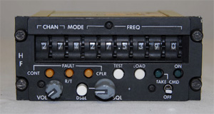 |
C-10828 Control - The control provides access to the 30 preset channels,
8 modes, 30,000 normal channels, test functions, squelch and power on/off. You should
know the 8 different modes of operation: UV (Upper Voice), LV (Lower Voice), UD (Upper
Data), LD (Lower Data), CW (Continuous Wave), AME (Amplitude Modulated Equivalent),
P (Preset) and A (not used).
Continuous Wave is seldom used... it's basically for morse code transmissions. There are the 4 single sideband modes, which ought to be fairly self-explanatory. A is not used and will generate a control fault if selected. Preset accesses one of the 30 preset channels. And AME is simply AM transmission with one of the sidebands removed. Note that it is not the same as AM. Something every comm/nav troop needs to know about HF are the 3 user faults. The first, already mentioned, is a control fault generated by selecting A. You can also generate a control fault by selecting a frequency below the usable range (below 2 MHz). And finally you can generate an R/T fault by selecting an unused preset, since the presets are stored in the R/T. By default, a brand new R/T doesn't have any presets in it, so if you select a channel that has not had a frequency programmed into it, the control is simply trying to tell you that you aren't going to be transmitting on anything until you put something in there. |