| From: | Dave Deiter |
| Topic: | Multipak Interface 3024 patch for CoCo3 |
| Message: | 1 of 1 |
| Sent: | Sun, 19 Dec 1999 16:40:17 -0500 |
Soldering tip: Place
a small amount of solder on the pin first before attaching any wire. Wire
Wrap Wire is already tinned so just place the
wire against the
solder and lightly press against the wire with the soldering iron. As soon
as the wire sinks into the solder remove the iron and hold the wire steady
until the solder cools. As long as the solder wraps the wire you will have
a good connection.
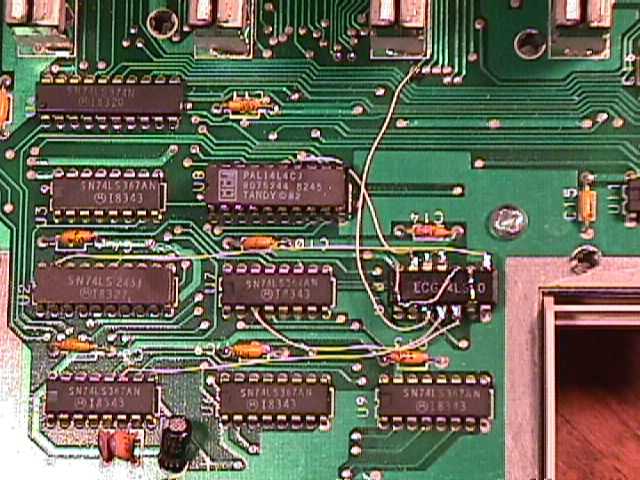
Prepare the 74LS10 by bending all pins except 7 and 14 straight out from the IC body, then continue by bending pins 1, 2, 6, 9, and 10 straight up from the body of the IC. Then bend the skinny part of the leg on pin 1 towards pin 14 until it is parallel with the top of the IC body. Now bend the skinny part of pin 2 towards pin 1 until it makes contact with pin 1. Bend pin 6 towards pin 9 until it's level. Bend pin 9 towards pin 6 until it's flat with pin 6. Bend pin 10 flat and twisted towards pin 1. With pins 11 and 12 bend the skinny part of the pins flat towards each other. Now apply solder to pins 1 and 2 also to pins 6 and 9 as well as 11 and 12. Now bare enough wire to connect from pin 1 to pin 10 and from pin 1 to pin 14. With pins 3, 4, 5, 8, and 13 bend the skinny part back and forth a few times till it breaks off.
Set the 74LS10 on top of IC U10 "74LS30" making sure it is oriented in the proper direction. There is a notch on the top of the IC. It should be in the same direction as all the other ICs. Solder pins 7 and 14 of 74LS10 to pins 7 and 14 of 74LS30. Now gently remove IC U8 "the PAL" from its socket and bend pin14 out a little so that when the PAL is placed back in the socket, pin14 is out of the socket. Put the pal back in its socket. Attach a wire from pin14 of the PAL to pin13 of the 74LS10. Now attach a wire from pin8 of the LS10 mod to pin19 of IC U2 "LS245", attach a wire from pin3 of the LS10 to pin40 of J2. When looking top down at the Multipak Interface with the slot select switch nearest you. J2 is the second slot away from the switch. Pin 40 of J2 is far left nearest you (this pin is common to all slots). If you look at J2 you will see a trace going to the left from pin40 at the left end of this trace is a small solder point. This is where you should connect this wire. Connect a wire from pin4 of the LS10 to pin11 of IC U1 "LS367". Connect a wire from pin5 of the LS10 to pin3 of IC U7 "LS367". This completes the patch.
Dave Deiter