INFORMATION SHEET 2 (COC 2)
SET-P COMPUTER NETWORKS
CABLING COLOR CODING
1. RJ45
A. B.
WG G WO Bl WBl O WBr Br WO O
WG BL WBL
G WBr Br
1 2
3 4 5
6 7 8 1 2 3 4
5 6 7
8
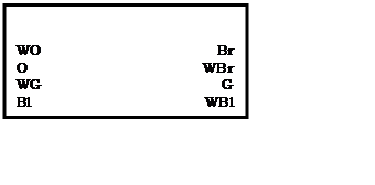
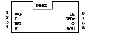
2. PATCH PANEL
A. B.
WBl Bl WG G
WO O WBr Br WBl Bl
WO O WG G WBr Br
1 2
3 4 5
6 7 8 1 2
3 4 5
6 7 8
3. MODULAR BOX
![]()
![]()
![]()
![]()
![]()
SAMPLE DIAGRAM
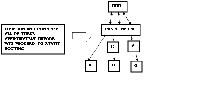
STATIC ROUTING
For Example, the GIVEN IPs are:
Router – 192.168.4.1
Server – 192.168.4.2
Client – 192.168.4.3
Router Name: Your Name
Router Password: Aguilar2021
PROCEDURES:
1. Reset Router (Long Press the BLACK BUTTON)
2.
Go to Browser and enter
the default IP Address of the router (192.168.0.1)
3.
Log-in as admin. The
default username is admin and the default password is
admin.
4.
Change Router name.
- Go to “Wireless”, change the wireless network name then save.
5.
Change Router Password.
- Under “Wireless”, go to “Wireless Security” and the Wireless Password to
Aguilar2021 as given.
6.
Change Router’s IP
Address.
- Go to “network”, click “LAN” then change IP Address to 192.168.4.1 as
given.
7.
Change Server’s IP
Address.
- Open “Network and sharing Center” then click “change Adapter Settings”.
Select and right click “Local Area Network”, click “Properties”, double click
the “IPv4”, click “Use the following IP Address”, then change the IP Address to
192.168.4.2 as given then click the subnet mask, ok, ok.
8.
Change Client’s IP
Address.
- Go to client, and do the same thing as what you did in the server and
change the client’s IP address to 192.168.4.3 as given.
9.
Turn off firewall.
-click “start”, type “fire” and click “windows firewall”. Click “turn
off firewall on or off” and then click “turn off firewall..”,
close.
10. Check of there are connections between
the router, server and the client.
- go to server, press windows + R, type “ping
192.168.4.1 –t” to check the network connection of the router
-
“ping 192.168.4.2 –t” to check the network connection of server
-
“ping 192.168.4.3 –t” to check the network connection of client
- do this also to the client*.
Name:____________________________________ Score:__________
Strand & Grade Level:________________________ Date:___________
PERFORMANCE TASK SHEET 2.1-4 (COC
2.2)
Title: Configuring
patch panel
Performance Objective: Given
are the following materials, you should be able to configure patch panel.
Allotted time 30 minutes.
Supplies/Materials: Working
UTP cable, patch panel, network cable tester
Equipment:
Steps/Procedure:
1.
Read information sheet 2.1-4
Patch Panel
2.
Configure your patch panel
Where:
Network
color standards=T568B
3.
Connect your working patch
cord directly to patch panel port (front) then insert the other end to network
cable tester.
4.
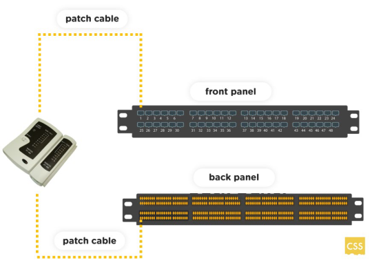 Connect
your patch cable (back panel) end to network cable tester.
Connect
your patch cable (back panel) end to network cable tester.
5.
Make it sure all the light
indicators are lightened up. A series of blinking lights will appear signifying
that the configuration is successful.
Assessment
Method:
Demonstration,
Observation
Performance
Criteria Checklist 2.1-4
Student’s
Name: ________________________________ Date:______________
During
the performance of the task, did you consider the following criteria?
|
CRITERIA |
YES |
NO |
|
Did the
student…. |
|
|
|
1.
Properly configured patch panel using T568B
color standard? |
|
|
|
2.
Successfully tested the patch panel
configuration |
|
|
|
3.
Applied and performed occupational health
safety procedures. |
|
|
|
4.
Performed and followed completely the give
task? |
|
|
|
Total Points |
|
|
|
Total Items |
|
|
|
Signature of
the Learner |
|
|
|
Signature of
the Teacher |
|
|
RUBRICS:
No. of Yes No. of NO Score Remarks:
7 7 100 Outstanding
5-6 5-6 93-95 Very Satisfactory
4 4 90 Satisfactory
3 3 85 Satisfactory
2 2 80 Fairly
Satisfactory
1 1 75 Fairly Satisfactory
0 0 70 Did
Not Meet Expectations
Prepared
by:
Checked by:
CARIDAD V. OROGO,MIT
Teacher
II
GLORY
T. JOVEN, EdD LPT
Principal
II