| Throttle Body Assembly |
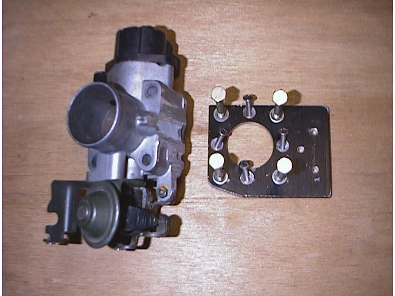 |
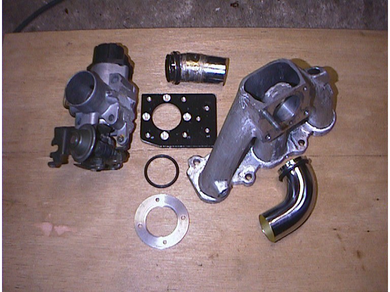
| This is the throttle body (TB) from an '87 Chevy Turbo Sprint after my band saw attack. On right, is a 1/4" AL adapter plate used to: 1) mate TB to the TB outlet which will feed manifold & 2) it also mounts assembly to cylinder head. The 4, 1/4" AL bolts secure TB to adapter plate & the 4 counter sunk bolts secures plate to outlet.backing plate ring. |
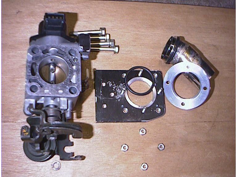 |
| This is outlet side of adapter plate & TB. The edge of the 1.5" hole was recessed to hold an o-ring. The outlet has a flange on its end. An o-ring is placed on both ends of the flange, the round AL backing plate ring is also recessed for an o-ring & is placed on the outside of the outlet flange & compresses the outlet to the adapter plate with the 4 counter sunk bolts. The outlet thus floats on the 2 o-rings. |
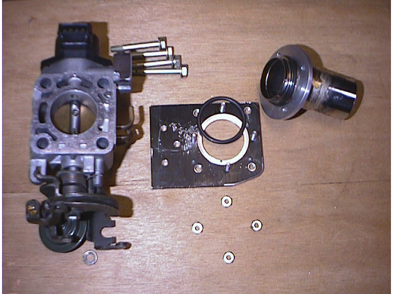 |
| Here the AL packing plate ring is assembled on the backside of the outlet flange. The outlet is made from commercial grade (20 ga.) brass sink plumbing. Brass work hardens with vibration, thus it floats on rubber. |
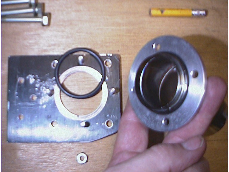 |
| Close up of adapter plate, outlet tube, o-rings & backing plate ring. |
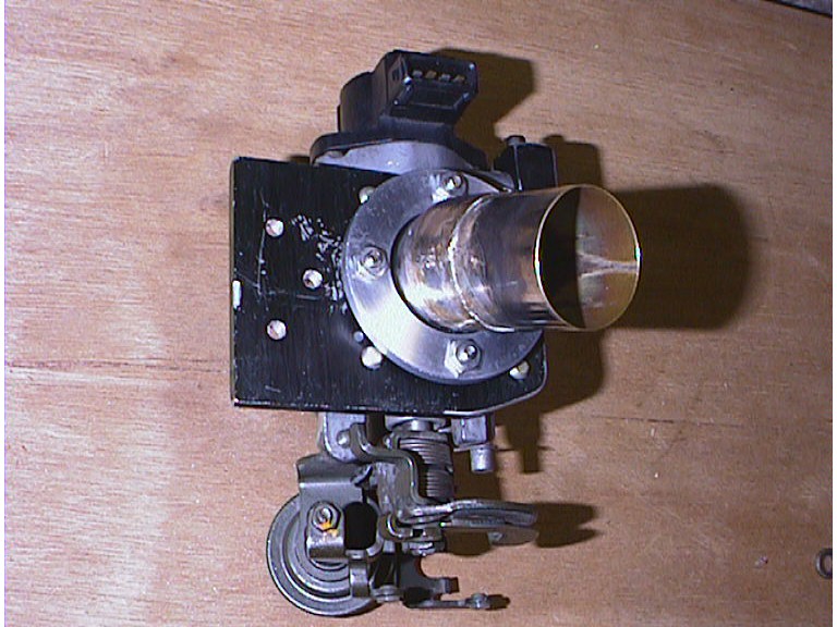 |
| Throttle body assembly with outlet mounted. At the top of assembley is the Throttle Position Sensor. It will be removes as its not needed with the Real Solution's computer system. |
 |
| redo this pic with backing plate for manifold feed outlet |