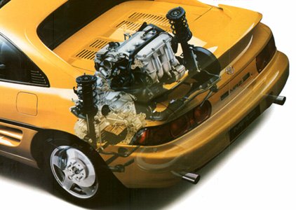
Ian's MR2 Page
 TB Page
 GEN3 3S-GTE PLUG ID
BA-1/EA-3(Engine Relay/Fuse Box 18 pin)
Loc. ID Color ’91 Gen2
18-1 TC on check connector White Same
18-2 TS on check connector Yellow Same
18-3 Intake Manifold Ground Wht/Blk Same
18-4 Alternator L Terminal Yellow Same
18-5 Igniter Black Same
18-6 Water Temp Sensor Yel/Grn Same
18-7 Oil Pressure Switch Yel/Blk Same
18-8 Ignition Switch Red Same
18-9 Not Used Brn/Blk A/C VSV
18-10 Not Used Yel/Blu A/C VSV
18-11 Not Used Red Oil Level Sensor
18-12 Not Used Red/Yel AB on Check Connector
18-13 Back-Up Light Switch Red/Blk Same
18-14 Air box Temp Sensor Brown Not Used
18-15 Not Used Not Used
18-16 A/C Magnetic Clutch Blk/Wht Same
18-17 Alternator S Terminal Wht/Red Same
18-18 Not Used- Pink Cruise Control ECU
Need to connect to 16-12 on engine ECU for gen3
AB-1/EA-1(Trunk Body Harness 15 pin)
Loc. ID Color ‘91 Gen2
16-1 Tranny Speed Signal Brn Not Used (Mech. Speedo)
16-2 Not Used Grn/Red Circuit Opening Rly to ECU 26-17
Need to connect wire from gen2 to engine ECU 22-14 for gen3
16-3 Eng Comp Temp Sensor Blu/Org Same/To Cooling Fan ECU #6
16-4 Eng Comp Temp Sensor Blue Same/To Cooling Fan ECU #5
16-5 Dash Warning Light Blu/Yel Same/To Cooling Fan ECU #2
16-6 Not Used Not Used
16-7 Not Used Wht/Blk Starter Relay #3
16-8 Engine Hood Switch Red/Grn Same (TDS)
16-9 Cat EGT Pink Not Used
Need to connect to engine ECU 22-16 for gen3
16-10 Tranny Speed Sensor Vio/Wht Same/To Cruise Control ECU
16-11 Dash Boost Gauge/PIM Blu/Blk Same/From TPS
16-12 F/P Check Connector Blu/Blk Same
16-13 F/P Relay Blu/Red Not Used
Need to remove wire engine ECU 22-6 from gen2 harness and connect here for gen3
16-14 Not Used Not Used
16-15 Check Engine Light? Grn/Wht Not Used
No connection
ELECTRONIC SPARK ADVANCE (ESA)
EXCEPT SUPRA TURBO
The ESA system replaces conventional mechanical and vacuum
advance. The ECU controls the ignition spark advance curve for every
driving condition. Spark advance is based on the following inputs:
coolant temperature sensor, O2 sensor, engine RPM, vehicle speed
sensor, A/C switch, 4WD operation (Land Cruiser, Pickup and 4Runner),
airflow meter and cranking (starter) signal. Integrated (coil in
distributor) and remote coil ignition designs are used, depending on
model.
On all models except Pickup (22R-E), Tercel and 4Runner
(22R-E), crankshaft position and engine RPM are monitored by the ECU
using permanent magnet pick-up coils in the distributor. Crankshaft
position is read by ECU at G1 terminal (and G2 on some models), and
engine RPM is input to ECU terminal Ne. See Fig. 23.
The ECU uses the Ne and G pick-up coil inputs to switch the
primary ignition circuit on and off. Primary circuit is turned off
when the ECU sends a signal to the ignitor on the IGT wire. At the
same time, the ignitor sends an IGF signal to the ECU. The ECU feeds
voltage to the IGF circuit. The ground for this voltage is momentarily
cut when the primary circuit is turned off.
The ECU watches the IGF signal and can tell if the primary
was switched on and off. After sending a command to turn off the
primary circuit on the IGT wire, the ECU monitors the IGF circuit to
ensure primary switching occurred. Normal cranking or running IGT
voltage is 0.60-1.70 volts.
NOTE: The TCCS system uses the input signal on the IGF line to
fire the injectors. If this line is open or shorted to
ground, the injectors will not fire.
On Pickup (22R-E), Tercel and 4Runner (22R-E), a single pickup
coil is used in the distributor. Ignition system operation is
similar to other models except there are no G signals. The ECU
monitors the pick-up coil signal at Ne terminal.
GEN3 3S-GTE PLUG ID
BA-1/EA-3(Engine Relay/Fuse Box 18 pin)
Loc. ID Color ’91 Gen2
18-1 TC on check connector White Same
18-2 TS on check connector Yellow Same
18-3 Intake Manifold Ground Wht/Blk Same
18-4 Alternator L Terminal Yellow Same
18-5 Igniter Black Same
18-6 Water Temp Sensor Yel/Grn Same
18-7 Oil Pressure Switch Yel/Blk Same
18-8 Ignition Switch Red Same
18-9 Not Used Brn/Blk A/C VSV
18-10 Not Used Yel/Blu A/C VSV
18-11 Not Used Red Oil Level Sensor
18-12 Not Used Red/Yel AB on Check Connector
18-13 Back-Up Light Switch Red/Blk Same
18-14 Air box Temp Sensor Brown Not Used
18-15 Not Used Not Used
18-16 A/C Magnetic Clutch Blk/Wht Same
18-17 Alternator S Terminal Wht/Red Same
18-18 Not Used- Pink Cruise Control ECU
Need to connect to 16-12 on engine ECU for gen3
AB-1/EA-1(Trunk Body Harness 15 pin)
Loc. ID Color ‘91 Gen2
16-1 Tranny Speed Signal Brn Not Used (Mech. Speedo)
16-2 Not Used Grn/Red Circuit Opening Rly to ECU 26-17
Need to connect wire from gen2 to engine ECU 22-14 for gen3
16-3 Eng Comp Temp Sensor Blu/Org Same/To Cooling Fan ECU #6
16-4 Eng Comp Temp Sensor Blue Same/To Cooling Fan ECU #5
16-5 Dash Warning Light Blu/Yel Same/To Cooling Fan ECU #2
16-6 Not Used Not Used
16-7 Not Used Wht/Blk Starter Relay #3
16-8 Engine Hood Switch Red/Grn Same (TDS)
16-9 Cat EGT Pink Not Used
Need to connect to engine ECU 22-16 for gen3
16-10 Tranny Speed Sensor Vio/Wht Same/To Cruise Control ECU
16-11 Dash Boost Gauge/PIM Blu/Blk Same/From TPS
16-12 F/P Check Connector Blu/Blk Same
16-13 F/P Relay Blu/Red Not Used
Need to remove wire engine ECU 22-6 from gen2 harness and connect here for gen3
16-14 Not Used Not Used
16-15 Check Engine Light? Grn/Wht Not Used
No connection
ELECTRONIC SPARK ADVANCE (ESA)
EXCEPT SUPRA TURBO
The ESA system replaces conventional mechanical and vacuum
advance. The ECU controls the ignition spark advance curve for every
driving condition. Spark advance is based on the following inputs:
coolant temperature sensor, O2 sensor, engine RPM, vehicle speed
sensor, A/C switch, 4WD operation (Land Cruiser, Pickup and 4Runner),
airflow meter and cranking (starter) signal. Integrated (coil in
distributor) and remote coil ignition designs are used, depending on
model.
On all models except Pickup (22R-E), Tercel and 4Runner
(22R-E), crankshaft position and engine RPM are monitored by the ECU
using permanent magnet pick-up coils in the distributor. Crankshaft
position is read by ECU at G1 terminal (and G2 on some models), and
engine RPM is input to ECU terminal Ne. See Fig. 23.
The ECU uses the Ne and G pick-up coil inputs to switch the
primary ignition circuit on and off. Primary circuit is turned off
when the ECU sends a signal to the ignitor on the IGT wire. At the
same time, the ignitor sends an IGF signal to the ECU. The ECU feeds
voltage to the IGF circuit. The ground for this voltage is momentarily
cut when the primary circuit is turned off.
The ECU watches the IGF signal and can tell if the primary
was switched on and off. After sending a command to turn off the
primary circuit on the IGT wire, the ECU monitors the IGF circuit to
ensure primary switching occurred. Normal cranking or running IGT
voltage is 0.60-1.70 volts.
NOTE: The TCCS system uses the input signal on the IGF line to
fire the injectors. If this line is open or shorted to
ground, the injectors will not fire.
On Pickup (22R-E), Tercel and 4Runner (22R-E), a single pickup
coil is used in the distributor. Ignition system operation is
similar to other models except there are no G signals. The ECU
monitors the pick-up coil signal at Ne terminal.