In order to experiment with Software Defined Radio (SDR), you'll need some sort of hardware to get the digitized data in. This article describe the idea on how to build another simple SDR frontend with what you already have : a TV+FM card based on the CX2388x (CX23880,CX23881,CX23882,CX23883) family chipset. With this TV card, you get a RF tuner and a high speed ADC. In our experiment, we use a PixelView PlayTV Pro Ultra TV+FM card. The result is a SDR frontend that can tune from 50 to 850 MHz and capture an intermediate frequency (IF) at a sampling rate of 27 MHz into 8 bit unsigned PCM data. IF of 10.7 MHz came from the tuner itself and is feed to one of the ADC input. IF bandwith is about 150-250 kHz due to filtering in the tuner itself. The capture program take the ADC data and write it to a file for offline processing. We use a Dell Pentium III 800 MHz PC for this experiment which is not fast enough to do real time processing on the captured signal. It is yet to be tested whether it is possible to do a real time FM radio demodulation on a faster machine for this SDR frontend which would otherwise be possible on other types of SDR frontend.
The CX2388x driver, raw data capture program, tuning program and a simple Python code using GNU Radio module to do FM radio demodulation are given below. As for hardware modifications, an exact descriptions will not be given since the steps might be different depending on the card that you have. Ideas are given and this should be enough for a qualified and trained person to do the modifications. Results from capture of a FM station are also presented.
For serious SDR experimentation, user should consider other readily available RF frontend. Some of them are :
Without modifying the TV card, it is still possible to do some a bit of SDR work. In this case, you can connect a video camera to the 'video in' of the card and capture this signal using software provided below. Instead of using a video camera, you can get the composite signal from the TV tuner itself but the tuner software provided below might not work with your TV tuner. So it will better if you apply the signal to 'video in'. A typical work that you can do with this setup is to write software to decode a NTSC/PAL composite signal. An interesting project related to TV composite signal will be DScaler project.
A simple SDR hardware frontend consists of
This hardware setup is not that ideal since it does not have a hardware digital down converter and decimator to reduce the sampling rate further. Nevertheless, we can still implement a down converter and decimator in software by sacrificing CPU power.
Back to the CX2388x TV+FM card, first, we will need the CX2388x datasheet. Google for 'CX23881 datasheet' to get a copy. Get the copy that describes CX23880/1/2/3. Next get a copy of TV/FM RF tuner datasheet for reference. Google for 'FM1216'. FM1216 is a Philips TV+FM tuner. Not all TV+FM card uses this tuner, if possible get the datasheet for the tuner on your card.
The CX2388x itself contains two high speed ADC capable of sampling up to 30 MHz at 8/10 bit. Of these two, only one is available for us to get the the raw sampled data. Four multiplexed inputs are connected to this ADC (pins called VMUX1 to VMUX4). Typically, these inputs will be connected to :
The idea now is to sacrifice either 'video in' or 'S-video in' so that this input is used as your ADC input. Tuner composite input will not be used since you will need to revert back the hardware modifications to watch TV on your PC. By choosing either 'video in' or 'S-video in', you can still receive TV stations and left with one usable video input (for your video player). We don't use the unused input since you will need to solder a DC blocking capacitor there. For the other inputs, the DC blocking capacitor should already be there. Once you have choosen the input, all the components (capacitors to ground, series inductor) along that input will need to be removed. The only component left is the DC blocking capacitor which is connected to the VMUX pin. The other end of the DC blocking capacitor will be your ADC input for SDR. Note there is no anti-aliasing filter here. The other way is that you find the DC blocking capacitor, desolder it, solder it back tilted so that it is connected to the VMUX pin only. The other end of the capacitor is not connected to anything and will be your ADC input. In this method, you only touch the DC blocking capacitor.
A typical TV tuner module will tune from 50 MHz to 850 MHz. Most or perhaps all TV card tuner uses I2C interface for tuning. The idea now is too look for the IF pin if present. The TV+FM card used for this experiment has a pinout similiar to the one shown in Table 1. Pin 22 will be our desired IF pin. This pin outputs a 10.7 MHz IF after passing through a 10.7 MHz surface acoustic wave (SAW) filter. The bad thing about this IF output is that the bandwidth is limited to about 150 to 250 kHz due to the SAW filter. This pin also might already be used on the TV+FM board itself and is connected to the CX2388x through some sort of filter circuits for FM demodulation in the CX2388x. You will need removed appropriate components so that this output is connected only to the ADC input of the CX2388x (with DC blocking capacitor). It might be possible to parallel both of these input but this has not been tried. Luckily, our board has a 0 ohm resistor at the IF output. We only removed this component and leave the rest of the filter components untouched. Figure 1 below shows the connections used in our board. Values used are as what is available at that time. For those having different tuner module, make sure the IF output signal is compatible in level for the ADC input.
Figure 1 (below) : Connection from tuner IF output to ADC input
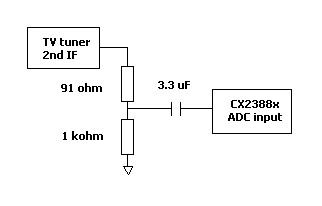
Table 1 (below) : Example of TV tuner pinout (extracted from FM1216 tuner module datasheet)
| Symbol | Pin | Description |
|---|---|---|
| VT | 11 | tuning voltage (monitor) |
| VS(tuner) | 12 | supply voltage tuner section +5V |
| SCL | 13 | I2C bus serial clock |
| SDA | 14 | I2C bus serial data |
| AS | 15 | I2C bus address select |
| AF O/P right | 20 | FM radio right channel |
| AF O/P left | 21 | FM radio left channel |
| 2nd IF sound output | 22 | second IF sound output |
| CVBS | 23 | Composite Video Baseband Signal (CVBS) output |
| Vs (IF) | 24 | supply voltage IF section +5V |
| AF outpu | 25 | AF sound output |
| - | TH1-TH4 | mounting tags (ground) |
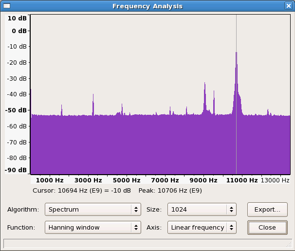
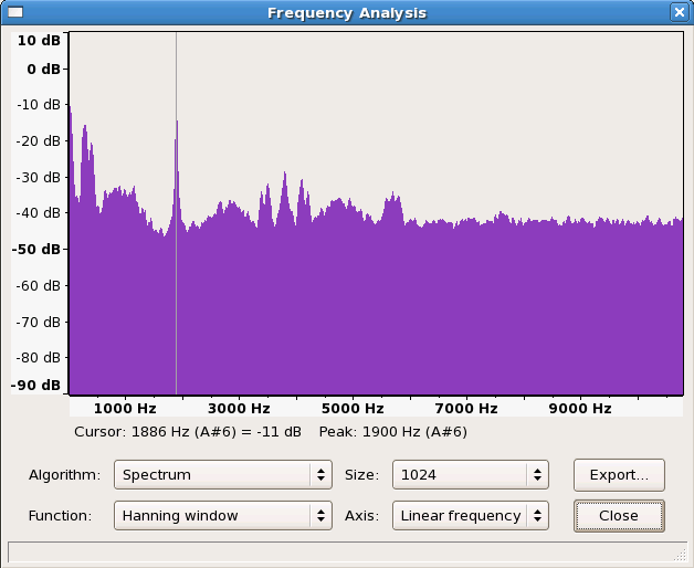
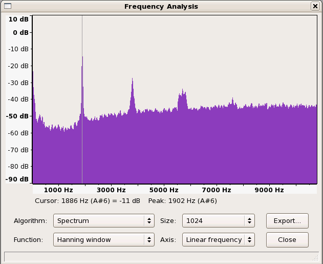
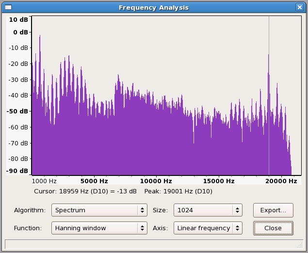
If all goes well, we will be able to capture IF signal from the tuner. Below are examples of spectrum at various stage of FM demodulation. Demodulation of captured signal requires GNU Radio package to be installed. The Python code that do this is given below.
Spectrum are ploted using Audacity. GNU Radio module itself has a FFT plot capability. However, we did not manage to get it to work yet. Therefore all data are imported into Audacity and spectrum plotted there. Due to whatever reason, Audacity does not plot the spectrum properly when high sampling rates are used. The sampling frequencies used during importing are scaled down so that the spectrum are ploted properly. Actual frequencies will need to be scaled up as mentioned in the caption.
Sampled IF from ADC for the FM output below is not available for download due to its file size. (~ 210 Mbyte for about 7.8 seconds of voice)
Demodulated raw PCM data file at 216kHz. zip file (~2.8 Mbyte). Format : sampling rate = 216 kHz, mono, 16 bit, little endian
Final FM demodulation raw PCM output at 43200 Hz. zip file (~ 581 kbyte, about 7.8 seconds of voice). Format : sampling rate = 43200 Hz, mono, 16 bit, little endianFinal FM output is available as a wave file. Exported to wave format from Audacity.
Driver, data capture and tuning program are developed on Fedora Core 6 running Linux kernel 2.6.18. Refer to the readme files and the source comment on how to compile and to use. Note that the driver (might) work only on Intel 32 bit single processor machine. Read the warning and what to expect section above before using this driver.
In order for this driver to run properly, the original TV card driver must not be loaded during Linux boot-up. For our case, we blacklist the TV card driver by inserting 2 lines below into the file /etc/modprobe.d/blacklist. Make sure cx8800 and cx88xx (or any other TV card driver) are not loaded using the 'lsmod' command. Removing these modules using 'rmmod' do not work.
blacklist cx8800
blacklist cx88xx
For FM demodulation, GNU Radio package need to be installed. We used version 3.0.2. Source code for GNU Radio package is available from www.gnuradio.org.
Python FM demoulation code is a modified code from GNURadio package. It is used to demodulate 10.7 MHz samples captured by this driver. To run this program, use the following command line.python fmrx.py
The input file is raw.pcm and the output file is audio.pcm. Output file format is 43200Hz 16 bit mono little endian PCM data. Wait some time for the program to process even after it print 'Print ENTER to quit:'. To run properly,we also added in the following line into .bash_profile file in order for Python to find the gnradio package properly. Change the path if GNURadio Python package is located at a different location.
export PYTHONPATH=/usr/local/lib/python2.4/site-packages
Download Python FM demodulation source code
There will be 3 files that need to be compiled. (more information are available in source and the readme files included with the source)
To compile, use the following command line to compile cxadc.c, cxcap.c and i2ctune.c respectively.
make
gcc cxcap.c -o cxcap
gcc i2ctune.c -o i2ctune
To install driver, log in as super user, and use the following command line.
insmod ./cxadc.ko
By default, the driver will take the ADC input from VMUX1. To select other ADC input, use the following command line. You will need to remove the driver first using 'rmmod cxadc' before installing again.
insmod ./cxadc.ko vmux=k
where k is from 0 to 3.
Next create a character device for cxadc driver.
mknod /dev/cxadc c 126 0
To capture data, run cxcap
./cxcap
By default, cxcap only capture 8 Mbyte of data into raw.pcm. To capture more data into a different file, us the following command
./cxcap 200 capture.pcm
This will capture 200 Mbyte of data into the file capture.pcm
To tune to a FM station, run the i2ctune program
./i2ctune
Key in the FM radio station frequency when ask to do so. After pressing ENTER, it should tune to that station. In TV cards similiar to the card we used, that station's audio will be available at the TV card audio output. If it does not, we suggest you shut down, power off and restart the machine in case the tuner program write some commands that can spoilt the tuner. See warning.
In the event the tuner program does not work, you will need to figure out how to tune the tuner ; either by modifying the driver and tuner code or to try this technique mentioned in the next section which could possibly work.
To remove the driver, the following command do.
rmmod cxadc
If the driver is not removed, the DMA keeps on running. You might want to stop it if you are not doing any more capturing.
Something to try in case tuner program does not workBefore trying to capture IF signal from the tuner (after hardware modifications), we suggest you try capturing signal from the video-in first. This is to ensure the driver is working. Try to feed the video-in with a composite video signal from a video camera. You can feed in other signal of correct amplitude but the video-in analog filters on the TV board might distort your signal. After succesfully capturing from the video-in, you can try the steps below which could possibly work in case the tuning code cannot tune your tuner.
If you intent to try out this driver, you should already have blacklisted the original TV card driver from loading during bootup. Now manually install those driver(s) using 'insmod'. Tune to a FM radio station using your original software. Reboot the machine (do not power off). The audio should dissapear from your speaker which is connected to the TV card. Install cxadc driver as mentioned above using the correct vmux input. Try capturing some data using cxcap and use, for example, Audacity to view the capture data to see whether a signal is there.