
BALTIMORE & OHIO RAILROAD CUMBERLAND DIVISION ELECTRICAL STANDARDS
WIRE COLOR CODE
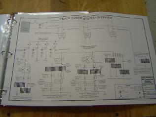
Colors are assigned to specific applications as defined herein. Do not mix colors in any application. That is a cause of maximum headaches later on when trying to troubleshoot or revise the railroad. Separate power zones can be identified by wrapping wire with colored identification tape after installation.
Black-- +12 Volt Track Power, direct or controlled through panel switches. Block detectors, when used , will be wired in the black side of power
White-- -12V Track Power, Wired directly to track-no controls or switches in this side of the power circuit..
Green-- Common for 24V (+12V,-12V) Switch machine power. and return for 12V signal/accessory power.
Blue-- +12V Switch Machine Power
Orange-- -12V Switch Machine Power
Yellow-- Switch machine control wiring between panels and switch machine motor
Gray-- Controlled power from panel toggle switches to track feeder terminal block.
Brown-- Power drops from turnout frogs.
Violet-- +12V for accessory power.
Red-- +5 V for electronics. now? Or future?


WIRE GAUGE
Proper wire gauge for each application is shown on layout electrical drawings. Some applications are presented below as a convenient reference.
12 AWG
Main track power buses from power supplies out around layout. Wires should
be twisted, one turn every six inches or less, to minimize RFI/EMI interference.
14 AWG
Track Circuits: Drops from main track power bus to circuit breakers.
Distribution buses from circuit breaker to Section Cut-off switches.
Distribution buses around the served power zone. Make them twisted pair as
done with 12 AWG main bus.
Switch Machine Power System: Main buses from +12 and –12 volt power
supplies including common return bus.
18 AWG
Track Circuits. Feeders from circuit breaker buses to terminal blocks connecting
track feeder drops.
Extension of track drops to terminal blocks.
Signaling and Accessory power: Main buses from power supplies to distributed
circuit breakers.
20 AWG
Track circuits. From control panel to track section (e.g. staging track)
where the track power is individually controlled by an operator.
22 AWG
Track circuits: Drops from individual rails to below roadbed. Some pre-existing
construction has used 24 AWG wire. New construction should use
22 AWG
Switch Machines: Wiring from control panel out to switch machine motor.
Wiring for frog power routing
Wiring for signals and CMRI applications to be determined. Small gauge multi-conductor cable may be applicable for these applications.
CIRCUIT BREAKER ASSIGNMENTS
Revised June 14, 2004
| Circuit Breaker | Location | Cut Off Switches | Railroad Area Controlled |
| CBA-1 | Near Stairway | S1 | East Yard-Body |
| S2 | Hump Yard-West Throat and Body | ||
| S3 | Hump Yard-East Throat | ||
| S4 | East Yard-Throat | ||
| CBA-2 | S1 | E/W main line to section break | |
| S2 | Interlocking | ||
| S3 | Main Line to Green Springs | ||
| S4 | Cutoff track to Western Maryland | ||
| CBB-1 | S1 | Turntable & Storage tracks | |
| S2 | Engine Terminal-all except turntable | ||
| CBB-2 | West Yard Throat Area | S1 | Arrival Yard-Body and West Throat |
| S2 | West Yard-West Throat | ||
| S3 | West Yard-Body | ||
| S4 | Arrival Yard-Throat to hump | ||
| CBC-1 | Cumberland City Area Main Lines | S1 | Pittsburgh Main Line |
| S2 | St. Louis Main Line | ||
| S3 | Cumberland Main Line | ||
| CBC-2 | Cumberland City Yards | S1 | City Yard & industry west of Balt. St. |
| S2 | City Yard to Baltimore St. | ||
| S3 | New Section & Wye-yard tracks | ||
| CBD-1 | Connellsville Staging | S1 | Kelly –Springfield Area |
| (Split panels 3/2) | S2 | Yard East Throat (left end) | |
| S3 | East staging tracks | ||
| S4 | West staging tracks | ||
| S5 | West Throat & Rev loop | ||
| CBD-2 | East of Junctions | S1 | Staging Connector |
| S2 | High Line-Low Line Junction | ||
| S3 | Western Maryland Junction | ||
| S4 | Hancock Main Line | ||
| CBE-1 | Magnolia Cutoff Area | S1 | Western Maryland Main Line |
| S2 | B&O Low Line to Okonoko | ||
| CBE-2 | Grafton Yard Area | S1 | Grafton-East Throat & rev Loop-left |
| S2 | Grafton Yard- Body B&O low line | ||
| S3 | Grafton-West Throat –right end | ||
| CBF-1 | S1 | Okonoko Interlocking | |
| S2 | B&O High Line to Okonoko | ||
| CBF-2 | Green Springs | S1 | Main Line Okonoko to Green Springs |
| S2 | More Main Line TBA | ||
| S3 | |||
| S4 | |||
| CBG-1 | Near Green Springs | S1 | PPG Module |
| S2 | Wye & Green Springs Station | ||
| S3 | |||
| CBJ-2 | S1 | ||
| S2 | |||
| S3 |