Welcome to my New project. This time we will build a UHV PLL TV TRANSMITTER. We will use a MC44BS374TI from Freescale. MC44BS374 is audio and video modulator for use in Transmit Video and audio and similar device. These IC are the next generation of the MC44BC374TI with the following new features:
- TV output level 83dBuV
- 5V and 3.3V compatible I2C bus
- Logic Output Port pin (pin 3) available
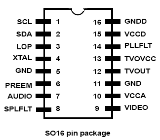
Figure 1 show the pin connections.

MC44BS374 IS a PAL/NTSC Modulator with Integrated VCO
The channel is set by an on-chip high-speed I2C compatible bus receiver. A
Phase-Locked Loop ( PLL )
tunes the modulator over the full UHF range.
The modulator incorporates a sound subcarrier oscillator and uses a second PLL
to derive 4.5, 5.5, 6.0,
and 6.5 MHz subcarrier frequencies. These frequencies are selectable by bus.
The picture-to-sound ratio may be adjusted using the bus. In addition, an on-chip
video test pattern
generator can be switched ON with a 1 KHz audio test signal.
The MC44BS374T1/374T1A have the following features:
• Integrated on-chip programmable UHF oscillator
• No external varicaps diodes / inductor or tuned components
• Extremely low external components count
• Channel 21-69 UHF operation
• VHF range possible by internal dividers (30MHz-450MHz)
• Boosted TV output level (82 dBuV typical) for the MC44BS374T1A
• TV output level of 75 dBuV typical for the MC44BS374T1
• High speed read and write I2C-bus compatible (800kHz)
• I2C-bus 5V and 3.3V compatible
• Fixed video modulation depth (82% typical)
• Peak White Clip disabled by bus
• Programmable picture/sound carrier ratio (12 dB and 16 dB)
• Integrated on-chip programmable sound subcarrier oscillator (4.5, 5.5,
6.0 and 6.5 MHz) - No
external varicaps
• On-chip video test pattern generator with sound test signal (1kHz)
• Low-power programmable modulator standby mode
• Transient output inhibit during PLL Lock-up at power-ON
• Logical Output Port controlled by bus
• Start-up on channel ‘71’ (871.25 MHz)
• ESD protection, minimum 4 kV
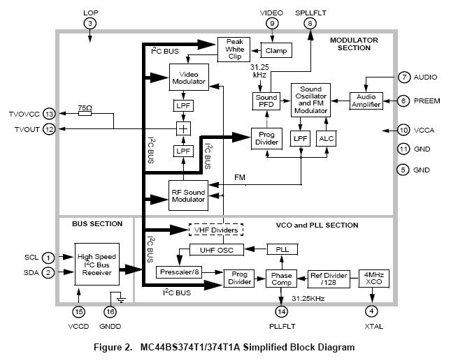
Figure 2 shows a simplified block diagram of the MC44BS374T1/374T1A device.
The MC44BS374T1/374T1A device has three main sections:
1. A high speed I2C-compatible bus section
2. A PLL section to synthesize the UHF / VHF output channel frequency (from
an integrated
UHF oscillator, divided for VHF output)
3. A modulator section, which accepts audio and video inputs, then uses them
to modulate the
UHF/VHF carrier
An on-chip video test pattern generator with an audio test signal is included.
The MC44BS374T1/374T1A operates as a multi-standard modulator and can handle
the following systems
using the same external circuit components: B / G, I, D / K, M / N.
High frequency BiCMOS technology allows integration of the UHF tank circuit
and certain filtering
functions.
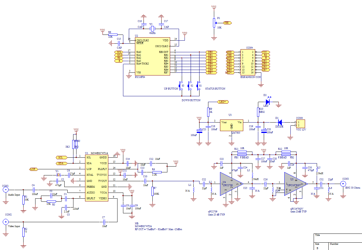
Now, its time to build a project. Take a look the schematic. If you can't see with clear the image, you can download it in PDF format from this link. Right click and choose save as to download it.
SCHEMATIC DESCRIPTION
A MC44BS374 R.F Modulator I.C is used to provide the R.F output and amplified by RF IC UPC2709 and UPC1678GV. It will have output about 17mW. The modulator is controled via microcontroler I2C interface and can tune the R.F Output to broacast channel. Microcontroler will set the frequency to 471.25Mhz - 895.750Mhz and have frequency step 250Khz. The modulator can set to VHF, it only depending on which software is used.
The modulator IC has two input. One called Audio Input, and one called Video input. You can directly attack your VCD/DVD output to this modulator and transmit to UHF frequency.
To change frequency use either up or down buttons, it will change frequency with 250Khz. Status button will have some function: Read Memory, Write Memory, Reset Memory and Lock status of the modulator.
The microcontroler is used to control I2C and drive LCD 2x16 Display. it will set the frequency, PWC (Peak white clip) default is on (System B/G), Sound Carier default is set to 5.5Mhz (PAL System), Picture to sound ratio 12dB, etc.
Component List
| Designator | Part Type |
Description |
| Y2 Y1 U5 U4 U3 U2 U1 S3 S2 S1 R8 R9 R7 R6 R5 R4 R3 R2 R12 R11 R10 R1 P1 L6 L5 L4 L3 L2 L1 FB2 FB1 D2 D1 CON6 CON4 CON3 CON2 CON1 C9 C8 C7 C6 C5 C4 C32 C31 C30 C3 C29 C28 C27 C26 C25 C24 C23 C22 C21 C20 C2 C19 C18 C17 C16 C15 C14 C13 C12 C11 C10 C1 |
4.000MHz 4.000MHZ UPC1678GV UPC2709 LM7805 PIC16F84 MC44BS374T1A Tictac Switch Tictac Switch Tictac Switch 22K 1K 100K 2.2K 3K3 3K3 15K 75R 10R 10R 1K 10K 10K N/A 56nH N/A 56nH N/A N/A F.BEAD F.BEAD LED 1N4002 VCC 12V LCD Connector BNC 50 Ohms Video Input Audio Input 100nF 10nF 10nF 27pF 470pF 100nF 22pF N/A 470pF 2.2uF 1nF 10nF 100nF 22pF N/A 470pF 1nF 22pF 100uF 100uF 22nF 100nF 100nF 27pF 27pF 100nF 10nF 10nF 10nF 10nF 10nF 220nF |
Crystal Crystal NEC RF IC NEC RF IC IC Regulator Microchip 8 bit Freescale IC Modulator Up Button Down Button Status Button Resistor SMD 0805 Resistor SMD 0805 Resistor SMD 0805 Resistor SMD 0805 Resistor SMD 0805 Resistor SMD 0805 Resistor SMD 0805 Resistor SMD 0805 Resistor SMD 0805 Resistor SMD 0805 Resistor SMD 0805 Resistor SMD 0805 Resistor SMD 0805 Not Used Inductor SMD 0805 Not Used Inductor SMD 0805 Not Used Not Used SMD Ferrite Bead 0805 SMD Ferrite Bead 0805 Diode LED Diode Power Connector 2x7 Header BNC Connector 50 Ohms RCA Connector RCA Connector Capacitor SMD 0805 Capacitor SMD 0805 Capacitor SMD 0805 Capacitor SMD 0805 Capacitor SMD 0805 Capacitor SMD 0805 Capacitor SMD 0805 Not Used Capacitor SMD 0805 Electrolyt Capacitor Capacitor SMD 0805 Capacitor SMD 0805 Capacitor SMD 0805 Capacitor SMD 0805 Not Used Capacitor SMD 0805 Capacitor SMD 0805 Capacitor SMD 0805 Electrolyt Capacitor Electrolyt Capacitor Capacitor SMD 0805 Capacitor SMD 0805 Capacitor SMD 0805 Capacitor SMD 0805 Capacitor SMD 0805 Capacitor SMD 0805 Capacitor SMD 0805 Capacitor SMD 0805 Capacitor SMD 0805 Capacitor SMD 0805 Capacitor SMD 0805 Capacitor SMD 0805 |
You can email me for HEX Code microcontroller for this project at [email protected]
SOFTWARE
Microcontroller was used for controling I2C bus for this device is PIC16F84, unfortunately this old pic has minim RAM. So i decided to developing with the big one, the PIC16F628. With this microcontroler it is posible to control all feature that have on MC44BS374. Here's preview
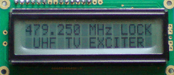
The picture to show LCD main display, you can see the frequency of the transmitter and lock status (LOCK) when is locked and text fail (FAIL) when the transmitter out of lock.
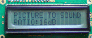
The picture to show LCD menu, it will show your picture to sound ratio of your transmitter. 16dB when byte PS (C1-High Order Bits 3) same as 1 and 12 dB when byte PS = 0. You can change the picture to sound ratio easily with up buttons.
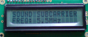
The picture to show LCD menu, it will show Sound Subcarrier Frequency, you can change it easily with up buttons. The option is 4.5Mhz, 5.5Mhz, 6.0Mhz and 6.5Mhz. This byte place at C0-Low order bits at bit 4 (SFD1) and bit 3 (SFD0), see datasheet.
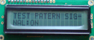
The picture to show LCD menu, it will show Test patern signal status, you can set to on/off with up buttons.
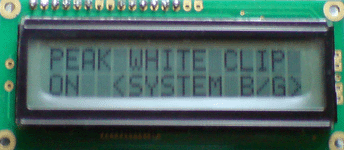
The picture to show LCD menu, it will show Peak White Clip of the transmitter, the option is on (for using system B/G) or off (for system L), to change it use up button when you show this message.
When transmitter power up, the LCD will show all config of the transmitter, and finaly show the frequency and status.
To change the config your transmitter press ST Buttons until you get the config that you want to change. Heres the list of menu:
1. Main Display, it will show your transmitter frequency, to change frequency press up buttons (for higher freq) and down button (for lower freq), it will change in step 250Khz.
2. VCO Status, you will see your vco status (in range or out of range). You can access this message with pressing ST Buttons one times.
3. Memory Read, you can access with pressing ST Buttons, to executed press UP Buttons.
4. Memory Write, you can access with pressing ST Buttons, to executed press UP Buttons.
5. Memory Reset, you can access with pressing ST Buttons, to executed press UP Buttons.It will reset your seeting to default.
6. Picture to sound Ratio, you can access with pressing ST Buttons, to executed press UP Buttons.It will change to 12dB to 16 dB and save it to memory directly.
7. Sound Subcarrier Freq, you can access with pressing ST Buttons, to executed press UP Buttons. The option is 4.5Mhz, 5.5Mhz, 6.0Mhz and 6.5Mhz
8. Test Patern Signal, you can access with pressing ST Buttons, to executed press UP Buttons, The option is OFF and ON.
9. Peak white clip, you can access with pressing ST Buttons, to executed press UP Buttons, the option is ON (SYSTEM B/G) and OFF (SYSTEM L)
The frequency range was set by software from 471.250 Mhz to 895.750 Mhz.
If you need the Hex code you can email me at [email protected]. I am offering pre-programmed Microcontroler (PIC16F628). The price is $10 (The Pre-programmed PIC16F628 was inluded)
Or you can download the TRIAL hex code directly, please click here .
If you use The TRIAL hex code, some feature will disable. Frequency locked in one frequency.
Will updated if any change required. Thanks