|
Main >
Equipment >
Locomotives >
P&W #1801 Project
|
|
|
 |
|
As a Providence & Worcester modeler, I quickly seized the opportunity with the launch of the Yahoo! Groups Internet U18B project led by Jim Six and Mike Rose. Although Jim is tackling the SCL and Mike the MEC/GTI, I quickly noted that P&W had their own U18B, #1801. As this was my first locomotive project, I appeciated being mentored by those who are admired for their own skills. Unfortunately, I also quickly realized that every single locomotive is different in their own ways and I had to deviate from both Jim and Mike. This further bolstered my confidence as I took on this project. I also was inspired by Robert Hargrave's diary of his MP 890 GP38-2 to document the chronology of my own project in cyberspace.
Image Source:http://www.rr-fallenflags.org/ |
|
|
|
 |
|
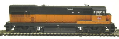
Here is a picture of the "donor" to the U18B project. Rather than use an Undec Atlas U23B, I happened to have a Milwaukee Road #5001 available. The only additional requirements are to strip the existing paint.
Material List
- Atlas U23B MILW #5001 w/FB 2 Trucks, 150-8673
|
|
|
|
 |
|
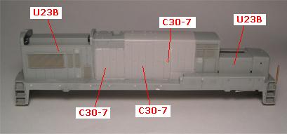
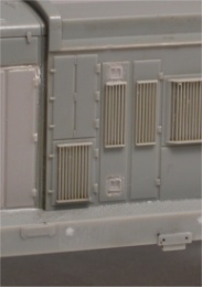
Step # 1: Shell Modifications - The picture to the left is the assembled shell identifying where each section originates. As the later phases of the U18B have some characteristics of the Dash-7 production, a C30-7 shell is used for the middle section of the body. Unfortunately, I didn't have photos of the original U23B or C30-7 shells prior to cutting or the individual pieces cut up. Due to difference in the gray colors of the stripped U23B and the undec C30-7, it is easy to identify where the cuts are made in the shells.
Material List
- Atlas C30-7 Body Undec, 150-860200
|
|
|
|
 |
|
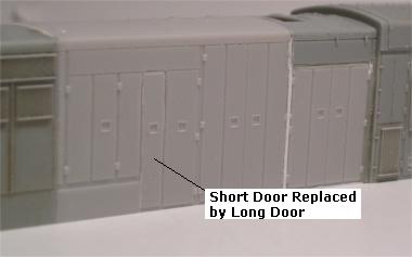
Step # 2: Assemble Shell - This steps continues with the actual assembly of the U23B and C30-7 pieces. Again, as I do not have photos specific to this step, I will highlight another modificiation to the shell. The 4th short door from the front on the C30-7 section needs to be replaced by a longer version. This door was taken from the discard section of the C30-7 shell. Note the use of .010" styrene strips to fill any gaps between the sections.
Material List
- .010" Evergreen Styrene strips
|
|
|
|
 |
|
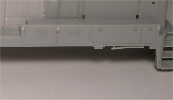
Step # 3: Walkway Modfications - In this step, there were supposed to be some discrepancies
with the battery boxes on the U23B walkway and this particular section was to be replaced with the battery boxes from the C30-7 walkway. As I studied this over and over and even consulted with Mike
Rose, I could not see the discrepancy and kept the U23B walkway as is. This, given that I even picked up (and cut up) the C30-7 walkway.
Material List
- None. (I can't count the walkway)
|
|
|
|
  |
|
Step # 4: Latch Modifications - This step is where the round door latches of the U23B are replace with the square latches that are characteristic of the Dash-7 production units. There were a total of 5 latches that were replaced by drilling out the round latches with a small drill bit and filing to a square opening. The square latches were salvages from the C30-7 body. For the rear door, I was not sure if the round latch was replaced or not. The only semi-convincing picture I found that helped me out was here, so I replaced the entire door from the C30-7 shell. Additional notes: I had to repair the rear left corner due to some "handling" damage and the existing stanchion holes were filled with styrene.
Material List
|
|
|
|
 |
|
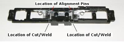
Step # 5: Shorten Frame - Based on the comments on the U18B Project Yahoo Group, it seems like this step is the biggest challenge on this project. I looked for a local machine shop to do the prescribed work, but most of them do aerospace work for P&W (Pratt & Whitney, not Providence & Worcester RR) and could not do it inexpensively. So, I decided that I would tackle the project myself. First rule was to be patient. If I got too anxious or started making mistakes, it was time to hang it up. The tools I used are as follows:
- Fine Razor Saw
- Dremel Tool with grinding attachments, various collets and drill bits
- Pin Vise with small drill bits
- Various files
- Hobby Mitre Box
|
|
|
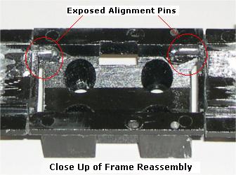
All cuts were made using the razor saw. This does take some time, but it does provide a good clean cut. There were a total of 4 cuts; one for each end and one to trim each side of the block covered up by the fuel tank. I was conservative on all my cuts leaving a little bit of extra metal, but too much and you find yourself with ALOT of filing. The next big challenge was the drilling for the alignment pins. I drilled the holes for each end section first. There is more material available in this section, but I needed to make sure they were located to provide the best location in the center section. One the holes were drilled (about 0.25" deep), I then cyanopoxied them into place. I then created a jig out of a block of wood to help align the center section with each end. I dabbed the tip of the installed pin with paint. This help mark the location of the hole in the center section. I then used a small drill bit and the pin vise to drill a pilot hole being careful not to wander from the location. Once the pilot was drilled, I then used the dremel tool to drill the hole to the proper size. As I got to the correct bit size, I had to be careful as the alignment hole protuded into the body of the center section (see photo - exposed alignment pins). I then touched up the holes to tweak the alignment between each section with a small grinding tip in the dremel and the filed to get the length correct with a file.
Material List
|
|
|
|
|
 |
|
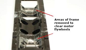
Step # 6: Frame Milling for Motor - Due to the shortening of the frame, it is necessary to mill out the necessary clearances in the frame for the flywheels. Again, this was done with a combination of razor saw and Dremel tool with a grinding and cutting tool. Manually intensive, but it works.
Material List
|
|
|
|
 |
|
Step # 7: Shorten Driveshaft - Again, due to the shortening of the frame, it is also necessary to shorten the driveshaft on each end that drives the truck drive mechanism. Determining the length of the cut to be made to the driveshaft was a little "trial and error" based on Jim and Mike's calculations. Rather than using the K&S Aluminum tubing or the Plastruct Plastic tubing, I ended up using Evergreen Styrene Tubing.
IMPORTANT NOTE: When I originally did the measuring for the driveshaft, I had the FB-2 trucks installed on the engine. However, as I am modelling the later version of the P&W unit, these trucks were switched out for the Alco AAR Type B trucks. Needless to say, during the steps for detailing the trucks I installed the new trucks donated from another U23B onto the frame and realized that these trucks are dimensionally different and the driveshaft is too long. Rather than redo the driveshaft, I ended cutting off approximately 3/32" off the end of the Female Worm Shaft Universal. Everything now seems to fit better.
Material List
|
|
|
|
 |
|
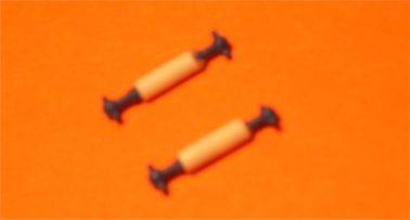
Step # 8: Drive Shaft Assembly - Here a photo of the assembled driveshaft mechanism with the AAR Type B trucks.
Material List
|
|
|
|
|
|
Step # 9: Motor Mounting - In this step, I followed Mike's lead and used the standard Atlas mounting mechanism and did not permanently mount the motor to the frame.
Material List
|
|
|
|
 |
|
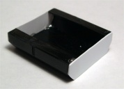
Step # 10: Fuel Tank Modifications - In this step, the fuel tank needed to be shortened to 11 scale feet. Prior to cutting the tank, each half of the U23B fuel tank were cemented together. Then an equal amount was cur from each end of the tank. Added .020 sheet styrene for fuel tank ends. I then used .040 sheet styrene on the inside end walls to add more strength to the ends. Drilled 4 holes in bottom to gain access to the screws holds the motor to the frame a la Mike Rose.
Material List
- .020" Evergreen Sheet Styrene
- .040" Evergreen Sheet Styrene
|
|
|
|
|
|
Step # 11: Fuel Tank Details -
Material List
- Airtank Kit For 4 & 6 Axle GE Locos, Details West, 235-263
- EMD Flush Mount Fuel Gauge, Details Associates, 229-3101
- 0.015" Phosphur Bronze Rod
|
|
|
|
|
|
Step # 12: Truck Details - The detailing of the trucks was a step that I was kind of on my own with, as my project was the only one with the AAR Type B trucks. The areas I would focus on would be the brake line piping, sanding pipes, Timken bearing caps and a single wheel slip modulator.
For the brake line piping, I first trimmed off the molded on piping coming out of the brake cylinder and across the middle of the sideframe. I also trimmed the brake cylinder itself (it's not round) and the back of the truck to allow better clearance of the brass rod (requiring fewer bends) from one cylinder to the next. I used 0.020" brass rod for the brake pipe. To mount, I drilled a hole in the cylinder (note, it's hollow!) and cyanopoxied the rod to the back face of the sideframe only.
The sanding pipes proved to be more difficult. I originally removed the sideframes to drill the mounting hole and install the 0.015" phosphur bronze rod. Unfortunately, with the AAR Type B trucks there is almost no clearance between the truck and the air tank cylinders on the fuel tank. After looking at some of the prototype photos that I have, they had the same problem on the prototype. So, I need to change the bending in the sander pipes to allow for non-prototypical radius turns.
The next step is to drill out a 1/8" hole in the bearings to allow the installation of the Timken bearing caps. Only the later version of #1801, there was only the single wheel slip modulator, which is installed as shown.
Material List
- Axle Bearing Cap (7), Details West, 235-244 (4 per pkg)
- Wheel Slip Modulator, Custom Finishing, 247-195
- 0.020" Brass Road
- 0.015" Phosphor Bronze Wire
|
|
|
|
|
|
Step # 13: Install Brass Steps - This is the first step where I consciously deviated from the Internet Group project. Upon receiving a detail photo of the rear pilot and steps, I saw the opportunity to add this detail to my project.
Material List
- Brass Diesel Steps For Railpower Shells -- B23-7, A-Line Products, 116-29233
|
|
|
|