Now Kaboom is Kaboom!
| ATARI
2600 / PC Now Kaboom is Kaboom! |
|
Idea & realization: Hernan C.
This report explains how to connect an Atari 2600 Paddle to the PC, by means of the use of a standard PC mouse board as the interface.
The advantages of this system are that it works with any Atari emulator (that accepts mouse) and it doesn't require any software or extra controller, since the Paddle will behave as a normal PC mouse. This device is also good for other emulators like 'MAME' (to play 'Arkanoid' in a much more realistic way!). As disadvantage, for the implementation of this system, You need to modify the Paddle and aslo You should dismantled a mouse wich will be unusable, however the modified Paddle will serve as much for the PC as for the real Atari.
This device works fine as much for the PC as for the Atari and it was tested in several situations and different hardware by using the emulators 'Z26' and 'Mame'. However, no responsibility will be accepted by hardware and/or software flaws (Atari2600/PC), neither no operation guarantee will be given. The application of this technique will be at your own risk.
Required elements:
- A pair of Atari 2600 Paddles (only one will be used) |
 |
| - PC mouse, It's highly recommended a simple and cheap one like 'Genius easy' or 'Mijuki' (5-10$) |  |
| - 2k Resistor (golden, red, red, red) |  |
| - Pieces of thin cable |  |
| - Welder, tin, screwdriver etc. |
Description:
The system is based on adapting inside of one of the Paddles a mouse board, coupling the wheel of the mouse horizontal control to the middle of the Paddle regulator and connecting the terminals from the shot button to the points of contact of the mouse primary button.
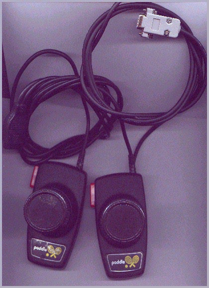
Here you can appreciate the (Image) of the Paddles, notice you the plug and the extra cable of the Paddle #1 which connects the mouse circuit in the PC.
 |
Connection
scheme showing the Atari Paddle onto the PC through the
extra plug. (the original plug should remain disconnected!) |
 |
Connection
scheme showing the Atari Paddles onto the Atari 2600
through the original plug. (the new plug should remain disconnected!) |
Preparing the mouse board...
For this project will be necessary to dismantle a PC mouse, by retiring the screws, the case, the ball and the wheels. Then you will have to remove the board connection cable (commonly 4 threads), please take note of the position that corresponds to each color (you will need to weld them again later).
To place this board inside the Paddle it is advisable to retire him all the buttom switches (so that it occupies less space), in this example only the central switch was removed and a hole was perforated in that place of the board; the screw that holds the paddle case will pass crossing that hole, however, it is possible that you can locate the board inside the Paddle in other position (then the hole is not needed).
Modification of the optic controls This procedure has the purpose to couple the optic part of the mouse board in the new position that will has the wheel (90 degrees angle). For this will be necessary to cut the part of the board which contains the horizontal movement controls, try to cut a minimum part of the board that contains the two optic components (typically one transparent -sender - and other black -receiver -). Don't worry about cutting the board furrows that correspond to these components, You will have to connect them with the thin cables making the connection to the points of the board that correspond.
Mouse board modification:
 |
 |
Keep in mind that the mouse board can be different but the basic components are the same for almost all the standard mouse. Notice: the colors of the treads are aleatory (only to show the 5 necessary extensions to make functional the separated board part).
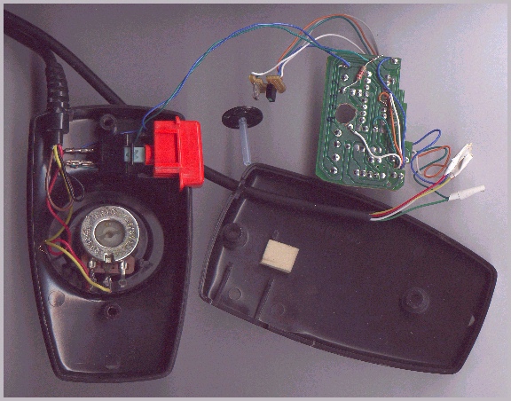
Preparing the paddle...
Once you have clever the mouse board You will have to perforate a hole in the back case of the Paddle to allow to pass the new cable, since now the Paddle contains two cables (the original which connects the Atari and the new one which connects the PC). Then you can insert the mouse cable in that hole and perform the necessary weldings to connect it again to the mouse board.
The last step to complete the electric part of the device is to connect the Paddle shot button with the primary mouse button. To get this, make a connection of one of the two terminals of the Paddle button with one of the three contact points of the mouse button switch (you can chose any except the one in the middle which is not used). Finally make a last connection of the other terminal with the other switch; however, in this case, will be necessary to insert the 2K resistor among this connection.
This image will clarify the concept:
 |
The new connection is marked with light-blue color. Only part of the mouse board is represented here, !Should NOT be interpreted like a broken board!
Note: It is possible to omit the use of the resistor if you plan to use the Paddle only on the PC, but, if you want this device works correctly also for the real Atari, You should include the resistor; else the shot button will act like continually pressed.
Physical connection of the optic elements to the Paddle:
The last step to complete this device it is to connect (physically) the horizontal control movement of the mouse to the Paddle, for this, will be enough with placing one of the two mouse wheels in the center of the regulator (by using the hole in the regulator). The wheel should be approximately to about 5 mm of the regulator (to be able to insert the board part of the mouse that we cut previously which operates together with the wheel grooves). To get this will be necessary to cut the wheel axis a little bit and perhaps replacing it with some other stick or similar that adjust better inside the regulator hole (in this example a little piece of a pen cartridge was used).
Important!: This may be the more difficult task in the project, since the sender and receiver should fit perfectly in the wheel and they should be aligned with the wheel grooves, or otherwise it won't work due to the precision of the optic system. It is also necessary to pay attention at the orientation (if the board is placed in a bad position, the turn direction will be inverted -in that case you can remedy it easily by pressing the key [TAB] in the 'Z26' emulator-). To assure the little board on the regulator it is recommended to glue it with some adhesive that allows an easy removing, in case of bad alignment.
These graphics show how should be the joining:
 |
 |
The first image shows 'step to step' the joining, the second image shows how would be seen from the side.
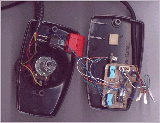
The following images show all the pieces that compose the finished device:
...Finally, assemble the Atari2600 Paddle again and enjoy it as much in this console as in the PC.
- Ending comments:
As you may suppose, to use this device in the PC, you first need to disconnect your habitual mouse to connect the Paddle. Nevertheless it is possible to maintain connected simultaneously both, please check out the following page to see how...
Click here to see the Suggestions and connection & configuration Tips.
IMPORTANT!: If you carry out this work, please send your comments it would be very appreciated , Good luck!
EnD.
*This material is exclusive property of Random'64 and cannot be used in any other publication without expressed authorization.
Contact | Random'64 Home Page | More docs
Copyright ©  .HCC. ~Software~ -2001-  Bs. As. (Argentina)
www.geocities.com/hcc.soft  ,  www.emuhq.com/random64