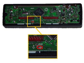
Modifications for the Icom

ก่อนอื่นต้องขอชี้แจงก่อนว่าข้อความทั้งหมดนี้ผมได้ก๊อปปี้มาจาก http://www.mods.dk/ ล้วน
เป็นภาษาอังกฤษทั้งนั้น และในบางหัวข้อที่เป็นการปรับแต่งวิทยุสื่อสารให้มีประสิทธิภาพยิ่งขึ้นทางผู้จัดทำ
จึงไม่ขอแปลเป็นภาษาไทย แต่ขอให้ผู้ที่ส
นใจทดลองเพื่อการศึกษาเท่านั้น เพื่อให้เป็นไปตามข้อกฎหมายของประเทศไทย


Modifications for the Icom 2100

 
21-03-1999
Icom IC-2100H Extended Transmit Mod
     
Please give us credit when copying these instructions!


  1. Hold down the second and third front function buttons while turning the radio on. Now turn it back OFF.

  2. Carefully remove the large tuning knob and remove the two hex screws that hold the faceplate on. Pull the faceplate straight of the body without tilting it (you run the risk of bending the pin connectors behind the faceplate).

  3. Turn the faceplate over and locate the main ic chip, set at a 45-degree angle. Just to the lower left and right of the IC, you will see the main pin connectors. Under the lower right corner of the left pin connector, you should see a marking on the pc board labeled as "D16". just below this should be the matching diode, close to the bottom edge of the board. Remove this diode and carefully re-assemble the radio(watch those faceplate pins!!

The radio will now TX 136-174 Mhz. As far as i know, you do not have to reset the memory to make the mod work( i have 70 out-of-band memories stored, all of them worked without resetting the unit!!!!!

September 5, 1998 - KC2AEI


Thanks to Chris KB3HPF for the pics.

Expand receiver for Ver #02. #06 and #07. (EUR version]

By key funktion:

  • Switch off the radio.
  • Push the [LOW/DUP] and [MONI/ANM] , while turning on power.

By diode:

  • Cut the D-16 on logic board. D-16 is located at centre, and below J2 and is the only NON-SMT diode.

After either mod, you will have:

136,000 - 174.000 MHz FM

(AM and 118 to 135,995 is NOT possible with the IC-2100H)


Modifications for the Icom IC-v8

 
08-01-2002
IC-V8 MOD for expanded RX/TX range. (136 – 174MHz)
     
Author: Scott KD4CWB - [email protected]


  1. Remove the battery pack.

  2. Peel off the black plastic panel on the bottom. (it will re-stick in place).

  3. With the white expansion connector on your left side, locate the series of diodes in the upper right side of the opening. Remove the diode located on the far left side on the lower row. (see photo or text diagram).
 ------------------------------------------------------_--------_-------_-----
|                                                     |o|   o  |o|  o  |o|    |
|                                                     | |      | |     | |    |
|     Option Connector                                |o|   o  |o|  o  |o|    |
|   ____                                               -        -       -     |
|  |                                                  ^                      |
|  | - - |                                             |                      |
|  | - - |                               Remove this   |                      |
|  | - - |                                diode ONLY!  |                      |
|  | - - |                               --------------+                      |
|  | - - |                                                                    |
|  | - - |                                                                    |
|  | - - |                                                                    |
|  | - - |                                                                    |
|  | - - |                                                                    |
|  | - - |                                                                    |
|  |____/                                                                     |
|                                                                             |
 -----------------------------------------------------------------------------
						Mod by:  Scott [email protected]


Modifications for the Icom 2GXAT

The ICOM 2GXAT HARDWARE MOD
     
  1. Open the radio by following the manuals instructions.

  2. On the half with the display and tone keys find the big chip (logic chip)

  3. To the right of it there are some small parts that look like this:
    |--------| 
    |  Logic |    XX     XX
    |  Chip  |         x
    |        |D14----> x XX  
    |        |     x x  
    |--------|    XX  XX  XX<-D13
    
  4. Remove both d13 (rx) and d14 (tx) and close the radio back up!

  5. Reset the CPU and you're done!

  6. If you mess up your radio I take NO RESPONSIBILITY. You do this at your own risk.
If anything you'll break the back light as most people do... But to help not do this the transistor d14 DOES NOT LOOK LIKE d13!!!


This modification has been read 1225 times.

 
06-03-2002
Software mod, to open IC-2GXAT
     
This is a software mod to open up the receiver for the IC-2GXAT.

(YOU DO NOT NEED TO EVEN TAKE THE RADIO APART!)

  1. Turn off the radio.

  2. Press and hold the, F KEY, Scan and Dup keys.

  3. While holding all 3 keys turn on the radio, continue to hold the keys for about 3 seconds WAITING until the display returns to normal before releasing the keys.

I did this to my HT and it receives from 50Mhz – 204Mhz.


IC-2SAT out-of-band transmit mod
     
  • Remove the back cover as per instuctions on page 34 of your manual.
  •              o
           -------------
           :   /       :
           :  /        :
           -------------
            o        o
    
  • as indicated by the drawing one diode has to be added to complete the modification
  • Beside the lower right corner of the Main IC, there are 3 chip resistors. Just to the right of the resistors, you can see 3 silk screened dots surrounded by a portion of a rectangle where a factory diode package would have been. The new diode (1N914 or whatever you care to use) is placed with the cathode (band) to the top dot and anode to the lower left dot.
  • This completes the mod. The HT will now transmit throughout the 150-160 MHz range.
I have completed this mod and on my 2SAT and it and it works well. The components are very small and the soldering has to be precise, BE CAREFUL!!!


This modification has been read 1581 times.


Modifications for the Icom 2SAT

19-07-1998
Icom IC-2SAT enhancements
     

A friend of mine in Germany mailed me a *very* intriguing photocopy of a letter he received from someone who works for Icom-Europe. It's an internal ICOM memo with details on how to do all sorts of nifty tricks with the IC-2SE (which may nicely translate to IC-2SAT tricks).

I have attempted to exactly duplicate the memo below, mangled spelling, unclear passages, and all. I don't have an IC-2SAT service manual yet, and so I'm not qualified to say if this is all really applicable or not. And, the German at the closing is a mystery. I typed "fu:r" to indicate "fr". Anyone with more details, please let us know!

Bob Cromwell KC9RG
[email protected]

ps:
For the people asking "what was your original diode matrix, that appears at the end. There was some thought that the matrix programming changed after the first few (hundred? thousand?) models. This is from the schematic that came with mine, with serial number in the 9500's.

pps:
Before you ask "where's part 1", that was the article titled "Icom IC-2SAT", where I gave results of signal generator testing....

                                                ICOM (Europe) GmbH
                                                Himmelgeister Strasse 100
                                                4000 Du:sseldorf 1
                                                F. R. Germany
                                                Phone: 0211 / 34 60 47
                                                Fax:   0211 / 33 36 39
                                                Telex: 8588082 ICOM D
                                                To:  Icom Dealer
                                                Dusseldorf, 14.4.89

I C O M     S E R V I C E     I N F O R M A T I O N     I C - 2 S E

Push Key + switch on    Requested Mode                  Remark
LIGHT + MON             CPU RESET                       Clear all Memories
LIGHT + FUNC            FULL DISPLAY                    Display Func Test
-----------------------------------------------------------------------------
LIGHT + V/M             SIMPLE MODE                     Info on Equipment
LIGHT + C (SCAN)        MULTI-FUNCTION MODE             Details in Handb.
-----------------------------------------------------------------------------
LIGHT + FUNC + V/M      RECEIVER MODE (All Band)        All Band - no Tx
-----------------------------------------------------------------------------
1.  Start SIMPLE MODE   TRANSCEIVER MODE/               Tx only HAM-Band/
2.  Light + FUNC + C    multi-function mode             Rx see list below
-----------------------------------------------------------------------------
Extent Transmitter      Install Diode AD (D6)           Tx: 139-163 MHz (FM)

Manual AM/FM Mode Change all Bands:                     Rx Band Ranges:
1.  Change to RECEIVER MODE (not receive mode)           75 - 106 MHz (FM)
2.  FUNC + PTT (working in RECEIVER MODE)               108 - 130 MHz (AM)
                                                        138 - 169 MHz (FM)
Note:  (+)                                              174 - 192 MHz (FM)
1.  keep pushing each key at same time,                 204 - 243 MHz (FM)
2.  switch on equipment,                                250 - 291 MHz (FM)
3.  hold (about 4sec.) until "SET" appear,              310 - 370 MHz (FM)
4.  release keys and requested mode appear;

Easily tunning step change (5 - 50 KHz):
1.  push and hold FUNC key for 2sec.
2.  rotate TUNING CONTROL.
3.  Push FUNC to return to previous mode.
Frequency ranges are appoximately and not garantied. Receiver sensitivity garantied only in HAM-Band (144 - 146 MHz).

In RECEIVER Mode equipment running exclusively as a Receiver, cannot transmit at all.

Achtung:
nur fu:r den Fachha:ndler zum Zwecke des Service bestimmt. Es mu:ssen die Bestimmungen des Fernmelde-Anlagengesetz heachtet werden.


This modification has been read 1513 times.

19-07-1998
IC-2SA/E Frequency range expantion
     
 
  • Remove any diode position on D6
  • Install diode DA (code No. 1750000160) position D6
After this modification frequency lock range will be expand typicaly :
        RX (MHz)  :  108 - 140 (AM) , 138-169 (FM) , 310-370 (FM) ,
        TX (MHz)  :  139 - 163 (FM) ,

        -------------------------------------------------
        |                                               |
        |                                               |
        |                                               |
        |                                               |
        |                                       R R     |
        |                                       3 3     |
        |                                       9 8     |
        |                                      o        |
        |                               R R R ### <---  |
        |                               4 4 4 ###       |
        |                               1 2 3 o o R     |
        |                                         6     |
        |                  ___________            1     |
        |                 /                            |
        |                /                             |
        |               |       SP1     |               |
        |               |               |               |
        |               |               |               |
        |                             /                |
        |                 \___________/                 |
        |                                               |
        -------------------------------------------------
Yeah, the above is crude, just meant to give the relative locations of the mysterious diode, SP1, R38, R39, R41, R42, R43, and R61. The 3-terminal box with an arrow drawn to it (the arrow is in the original image) looks like the below. A diode is connected from the lower left tab to the upper tab.
                ___
                | |
        --------------------
        |       /          |
        |     ---          |
        |     /_          |
        |  ____|           |
        | /                |
        | |                |
        --------------------
         | |            | |
         ---            ---
diode matrix programming

To simplify/fool-proof this, if the schematic has:

(X) --->|--- (Y)
I'll say "from X to Y". From the "IC-2SAT IC-2SET SCHEMATIC DIAGRAM":
        Japan Version           D6:     DA115   from KEYI2 to KEYS2
        Europe Version          D5:     DA115   from KEYI0 to KEYS3
                                D6:     DA115   from KEYI2 to KEYS2
        Italy Version           D5:     DAN202U from KEYI1 to KEYS3 and
                                                from KEYI0 to KEYS3
                                D6:     DA114   from KEYI0 to KEYS2
        U.S.A. Version          D4:     DA115   from KEYI2 to KEYS3
                                D9:     ISS254  from KEYI1 to KEYS2
        Australia Version       D5:     DA114   from KEYI1 to KEYS3
                                D6:     DA115   from KEYI2 to KEYS2
        Asia Version            D4:     DA115   from KEYI2 to KEYS3
Now, can anyone use this to figure out the Icom-Europe memo???
Bob KC9RG
[email protected]


This modification has been read 1483 times.

19-07-1998
Icom IC-2SAT unpublished Specificatons
     

I have access to some test equipment at work and did some studies on this little marvel of a transceiver. Here are some of my studies I have found so far:

12 dB SINAD Receiver Sensitivity:
Frequency:         µV           dBm
80.00 MHz         217           -60
90.00 MHz          64           -70
100.0 MHz          18           -82
110.0 MHz           2           -101
140.0 MHz           .185        -122
150.0 MHz           .16         -123
160.0 MHz           .3          -117
170.0 MHz           .9          -108
180.0 MHz           17          -82
190.0 MHz           74          -74
191.61MHz         --- vfo goes unlocked ---

210.0 MHz          590          -50
220.0 MHz          590          -50
230.0 MHz         2000          -40
250.0 MHz          173          -62
260.0 MHz          340          -56
270.0 MHz           27          -78
280.0 MHz            4          -94
290.0 MHz            .7         -110
300.0 MHz            .38        -115
310.0 MHz            .5         -113
320.0 MHz            .275       -118
330.0 MHz            .23        -120
340.0 MHz            .23        -120
350.0 MHz            .32        -117
360.0 MHz            .4         -115
365.0 MHz            .72        -110
-------------------------------vfo goess unlocked-------------------
Transmit Power: Voltage input at Coaxial plug on top of radio versus Power output
15.0V      5.3W
14.0V      5.2W
13.0V      5.0W
12.0V      5.0W
11.0V      5.0W
10.0V      4.5W
9.0V       3.75W
8.0V       3.0W
7.0V       2.3W

Internal Battery Pack (7.2V):
HI power    - 2.5W  0.9A
LO power 3  - 2.5W  0.9A
LO power 2  - 1.3W  0.68A
LO power 1  - .4W   0.43A

13.8V input via Coaxial Plug on top of radio:
HI Power     - 5W    1.3A
LOW power 3  - 3W    1.0A
LOW power 2  - 1.4W   .76A
LOW power 1  - 0.4W   .5A


This modification has been read 1449 times.

19-07-1998
Software coverage mods, IC-2SAT
     
From: [email protected] (Steven Kraft)

Modifying the IC2SAT for extended receive is very simple if a certain diode was not installed at the factory, as was the case with my 2SAT.

Turn the radio off, simultaneously press [#],[B],[light] and turn it on. (The button is not labeled, it is on the side under the wrist strap.) Release those three buttons after the radio beeps. (I think that mine beeped.)

It can now receive over three large frequency ranges and will receive AM aircraft band transmissions acceptably. Experiment to find which frequencies you can get. The memory channel number will display the letter "U" to show that the PLL circuit is unlocked on frequencies that cannot be received. It will tune from 0-1300MHz but the operable ranges are not that big, its highest receiving freq is a little over 300MHz.

If that doesn't work, a diode will have to be removed. It is a glass diode mounted on the PTT switch circuit board, and I think it is the only standard component in that area. It is mostly surface mount components.

Standard disclaimers apply, since I cannot be responsible for whatever you may do if and when you must remove the front to look for a diode. (The owner's manual explains how to open the 2SAT.)

Steven Kraft [email protected] KE9RW to other hams


Hosted by www.Geocities.ws

1