|
Home
| |
Project Guide
Step 1:
Make a multiplexer 8 to 1 ,each input 16 bits.
Well this can be done using 16 multiplexers each 8 to 1, each multiplexer
will be responsible to choose a certain bit from the input buses.
For example, first multiplexer will take bit 0 from each input bus.
Note: there are eight input buses
Step 2:
Make a 16 bit register that can perform clear,load and increment
Note: You will find this register in the Archive.
And the instructions how to download it in the DownloadTips.
It is very much recommended to read the downloading instructions first!
Step 3:
Given this instruction set:
| Fetch | R'T0: | AR<--PC |
| R'T1: | IR<--M[AR],PC<--PC+1 |
| Decode | R'T2: | D0,...D7<--Decode IR(12-14), |
| | AR<--IR(0-11),I<--IR(15) |
| Indirect | D7'IT3 | AR<--M[AR] |
Memory Reference:
| AND | D0T4: | DR<--M[AR] |
| D0T5: | AC<--AC^DR,SC<--0 |
| ADD | D1T4: | DR<--M[AR] |
| D1T5: | AC<--AC+DR,E<--Cout,SC<--0 |
| LDA | D2T4: | DR<--M[AR] |
| D2T5: | AC<--DR,SC<--0 |
| STA | D3T4: | M[AR]<--AC |
| BUN | D4T4: | PC<--AR |
| BSA | D5T4: | M[AR]<--PC,AR<--AR+1 |
| D5T5: | PC<--AR,SC<--0 |
| ISZ | D6T4: | DR<--M[AR] |
| D6T5: | DR<--DR+1 |
| D6T6: | M[AR]<--DR, if (DR=0) then (PC<--PC+1) , SC<--0 |
Register Reference
D7I'T3=r (common to all register reference instructions)
IR(i)=Bi(I=0,1,2,...,11)
| r | SC<--0 |
| CLA | rB11 | AC<--0 |
| CLE | rB10 | E<--0 |
| CMA | rB9 | AC<--AC' |
| CME | rB8 | E<--E' |
| INC | rB5 | AC<--AC+1 |
| HLT | rB0 | S<--0 |
Make a macro for each register control.
That will be 5 control macros.
For AR,PC,DR,AC,IR
You will need also control macros for the following:
ALU (which is given in the archive)
S flip-flop (which is given in the archive)
Sequence Counter (which is given in the archive)
Tip: The sequence counter is found in the Xilinx Library "CB4RE"
And the I bit is implemented using a Flip-flop and will be loaded at R'T2
Step 4:
Make a 16-bit ALU
Step 5:
Make macro to control the common bus, i.e. to select which
register may put its value on the common bus
Note: This macro is given also in bonus zip in the archive.
Step 6:
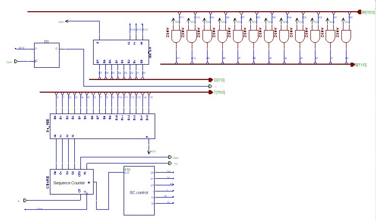
Make a macro for the control unit given on page 137
If you want to see a picture of how the control unit will look like click here:
Step 7:
At last connect all components as shown on page 130
If you want to see how the project will look like at the end click here:
and if you would like to enlarge it, click on it.
 Step 8:
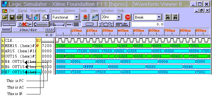
Never forget this step in any of your projects...Simulate!
Here you can view a sample of the simluation for
a given program:
| Memory Location | Instruction | [PC] | [AC] | [IR] |
| ORG 000 | 0000 | ---- | ---- |
| 000 | CMA | 0001 | FFFF | 7200 |
| 001 | INC | 0002 | 0000 | 7020 |
| 002 | ADD MIN | 0003 | 0050 | 1005 |
| 003 | AND MAX | 0004 | 0040 | 0006 |
| 004 | HLT | 0005 | 0040 | 7001 |
| 005 | MIN: HEX50 | | | |
| 006 | MAX: HEX60 | | | |
To view an image of the simulation click here:
|