The schematic is available in PDF format: Thermometer.pdf
Here is the code and project documentation:
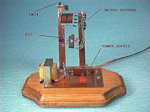
//-----< THERMO.C >----------------------------------------------------
// This is a very simple application showing the use of a LM34 temp.
// sensor driving the 16C71's A/D. The simplicity of driving a multi-
// plexed display is shown. The code simply alternates between one
// digit and the next to give the illusion of a two digit display.
//
// The LM34 outputs 10 mV / Deg F, it is scaled by the OPAMP to be
// 1 LSB per Deg F (Gain = 2) at the input to the A/D. This gives
// one degree resolution. The maximum temperature readout is 99 deg
// F, which is good enough for where I live, but you may need to add
// a digit (ouch, that's hot!).
//
// The digital thermometer was built on copper clad PCB material and
// mounted to a craft store wood base. It is self powered by the use
// of a Radio Shack AC to 12 V transformer and a LM7805
// voltage regulator.
//
// The thermometer can be powered by any 5 volt source, even a wall
// wart.
//
// The code is written in CCS PIC-C (www.ccsinfo.com)
//---------------------------------------------------------------------
//
// By: S.C.Hageman - 16Jan96
//
//---------------------------------------------------------------------
//
// Version Control:
// V.0 - Release 0 - 16Jan96 - SCH
//
//-------------------------------------------------------------------
//-----< Includes >--------------------------------------------------
#include <pic16c71.h>
#include <picbasic.h>
//-----< PCM Use directives >----------------------------------------
#use delay(clock=4000000)
//-----< Port definitions >------------------------------------------
#pragma byte port_a = 5
#pragma byte port_b = 6
//-----< Pin definitions >-------------------------------------------
#pragma bit Ones_column = port_a.2
#pragma bit Tens_column = port_a.3
//-----< Program constants >-----------------------------------------
#define DOOMSDAY 0
//-----< Program global variables >----------------------------------
int Display_value;
int Counter;
//-----< Display routine >------------------------------------------
set_digit(int value)
{
// Set proper values for drivers
// A zero value on the bit turns the segment on, hence the 0xff code
// turns all segments off. Bit 7 of port B is not used.
switch(value)
{
case 0: port_b = 0x40; break;
case 1: port_b = 0x79; break;
case 2: port_b = 0x24; break;
case 3: port_b = 0x30; break;
case 4: port_b = 0x19; break;
case 5: port_b = 0x12; break;
case 6: port_b = 0x02; break;
case 7: port_b = 0x78; break;
case 8: port_b = 0x00; break;
case 9: port_b = 0x18; break;
default: port_b = 0xff;
}
}
//-----< Main Program >----------------------------------------------
main()
{
// Set up the ports, clear them
#asm
// Port B to all outputs, then all off
movlw 0x00
tris port_b
clrf port_b
// Port A bits 0,1 to inputs, then the rest off
movlw 0x03
tris port_a
clrf port_a
#endasm
// Power up delay of 1 second
delay_ms(1000);
// Initilize A/D
setup_port_a(RA0_RA1_ANALOG);
setup_adc(ADC_CLOCK_INTERNAL);
set_adc_channel(RA_0);
// Initilize global variables
Display_value = 88; // 88 acts as segment test at start
Counter = 0; // Set sample counter to zero
// Main display loop
while(!DOOMSDAY)
{
// Sample temperature every 1 second
if(Counter >= 50)
{ // If here then it must be time to sample the sensor
// The 2 below is the offset value from the LM34 I used
Display_value = read_adc() - 2;
// Reset counter
Counter = 0;
}
else
{
// Increment counter
Counter++;
}
// Set ones column off
ones_column = OFF;
// Display tens value
set_digit(Display_value / 10);
tens_column = ON;
// Wait for multiplex time
delay_ms(10);
// Set tens column off
tens_column = OFF;
// Display ones value
set_digit(Display_value % 10);
ones_column = ON;
// Wait for multiplex time
delay_ms(10);
} // End of main while loop
}
//-----< Fini THERMO.C >---------------------------------------------
// Man this was an easy program to code.....SCH
Modified -
7Jan01