Any antenna used for transmission has the same goal. By generating an alternating current in a conductor, a rapidly changing electrical field is induced in free space. An electrical field cannot exist without a magnetic field component. These fields propagate until reaching another conductor - in which an alternating current similar to the original is induced. The only difference being the much lower energy level.
To make the transfer of energy from transmitter to antenna, and
from antenna to space most efficient, the antenna is made resonant - in other
words the alternating current flowing within the antenna swings to and fro at a
rate that matches the arrival of each peak of current from the transmitter. It's
like pushing a child on a swing - if you push at the same rate that the swing is
moving, you get bigger swings for your effort...
A magnetic loop antenna is so called because unlike a conventional wire dipole the small transmitting loop aims to generate the magnetic field rather than the electrical one. The result is the same once the radio wave is produced. Both the magnetic and electrical components propagate as before. The significance of generating a magnetic field lies in the tendency of magnetic fields to be captured by nearby conductors, but to be less affected by nearby ground. This may be because the magnetic field falls away more rapidly with distance than the electric field. This doesn't mean that small loops prefer being near the ground - but it does seem to suggest that they may be happier than the equivalent 'electrical' antenna at the same hight. Very low dipoles tend to radiate straight up!
Even a single, straight wire conductor has an electrical and magnetic field around it so long as the current flowing in it varies over time. However by coiling this conductor, the magnetic lines of force are concentrated (this is the basis of an electromagnet). Small transmitting loop antennas, are therefor small (single turn) coil antennas! Multiple turn STL antennas have been sucessfully built and used.
The resonance of a dipole antenna is determined by its size - the smallest resonant length is a half wavelength long (slightly smaller in fact because radio frequency travels more slowly in a conductor than in free space ). It is this 'half-wavelength limitation' that gives the magnetic loop its sense of appeal, or even dare I say, mystery?
A magnetic loop antenna is comprised of a (usually but not
necessarily) round conductor of a total length perhaps one quarter ( Roberto
I1ARZ Radio Communication March 1992 p66-68 and April 1992 p30-31) or more
commonly for short wave one fifth or one eight of a wavelength. (Henk G4XVF
Radio Communication Sep 1991 p51)
Loops made from conductors longer than
a quarter wavelenght, probably behave more like delta loop
antennas.
Since frequency multiplied by wavelength always equals the
speed of light, the higher the operating frequency, the smaller the half wave
antenna can be. This isn't so small. The magnetic loop, or small transmitting
loop (STL) antenna appears to offer some performance without needing that
mystical half-wavelength measurement. Indeed the whole operation of magnetic
loops generates considerable debate. The pivot of this argument is the
possibility that a small magnetic loop might be as effective as a half wave wire
antenna. It is surprisingly difficult to establish one way or the other as to
whether this is in fact the case.
Luckily, it doesn't matter! Once you have a system that your
transmitter can satisfactorarily load, you have an antenna that you can
use..
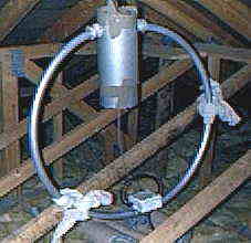
The STL is a physically small loop, usually of a single turn
but sometimes more - of a conductor which is less than one quarter of a
wavelength long. This single loop is resonated at the desired frequency by a
large adjustable air spaced capacitor that completes the circle (or whatever
shape the conductor happens to be).
This capacitor/loop combination is fed RF at its resonant
frequency either from smaller nearby loop, or a direct tapping of the coax from
the transmitter. Such loops are simple to build, and are regularly a solution
when a transmitting antenna for shortwave frequencies is needed indoors, in a
very small garden, to be hidden, or where there is local electrical
interference, or a high density of broadcast television receivers. Of proven
value to radio hams and international embassies alike. There has been one on the
cruise liner the QE2.
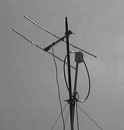
Following a recent house move I have relocated one of my long
suffering loops, the smaller (snow covered) one, inside - and it now sits
comfortably in the roofspace.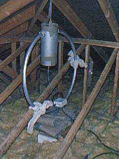
If you suspend a tyre vertically from a rope, and then look
through the 'hole', you are looking along the only point of a magnetic loop from
where there is no radiation- a NULL. The fact that this occurs at right angles
to the vertically standing loop does not significantly affect its radiation
pattern at shortwave frequencies. This is because useful radiation for
transmitting purposes leaves the attenenna at a high angle (for local contacts)
and a low angle (but not zero degrees) for long distance contacts. Radiation
leaving at zero degrees is likely to go to ground. However this null (which
applies on transmit and receive) can be pointed at a local source of
interference, or at an object that is being interfered with by the transmitter
with some benefit. Point the null at your TV feeder downlead for
example?
If you consider radiation a few degrees above the horizontal,
the STL approximates to an omnidirectional antenna with a significant
radiation at high angle. This is a further consideration when evaluating the
performance of STLs - dipoles are anything but omnidirectional - their null
along the direction of the wire, being much broader. An antenna that radiates in
more directions will radiate a weaker signal - but will work in more
directions...
"There is a strong, horizontally polarised field, radiated from a vertical loop...this component is retained (dominantly) in the far field". (G3LHZ ,Radio Communication TT Feb 98 page 63) although it is hard to see why there isnt a strong vertical component too. Perhaps this is a feature of the (a) the usually conductive vertical mounting post and (b) the fact that the capacitor, placed at the top or bottom of the loop presents a current minimum, but the two arms of the loop either side have current maxima in opposite directions, closely approximated- and thus may cancel out?
Email
GW0TQM
Carl GW0TQM's
Magnetic loop page
Contributions comments and STL links welcomed.
Magloop home What? Using Building BASIC Software Links More reading and reports
Sign the
Magloop Guestbook ![]() View the
magloop Guestbook
View the
magloop Guestbook