FDK Multi750 * Mic wiring, Servicing and alignment details*
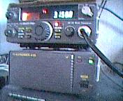
The FDK Multi-750e was launched in the
UK in 1981. A 2m ham radio multimode tranceiver, at a good price, and with a
matching 70cm transvertor controlled from the front panel. There are still a
good number around, but many have stopped working because of a very common fault
- the potentiometers on the PCB were verry prone to intermittent working -
especially on the final amplifier board.
If you have one with problems, it
really is worth giving all the pots a good clean, and sweeping the boards for
'dry' solder joints. Meanwhile I have a copy of the service manual as a series
of GIF images which you can view and print out here.
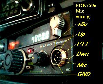
The FDK750 is fitted with a 6 pin microphone socket.
used on packet or APRS A 2.5mm loudspeaker jack at the back of the FDK carries received audio to the TNC. Both TX and RX
lines into the TNC are through a 180 degree 5 PIN DIN socket. The cable into the
TNC is screened.
Clockwise from the indentation in the socket, looking at the radio mic
socket:-
- Earth
- +5V
- Up
- PTT
- Mic
- (centre pin) Down
Multi 750e Servicing and alignment:
Click on each page to view it. These are GIF format files, and if you print them out- each should be put onto a single page of size A4- to give the best resolution.
All of the image files together add up to 2MB.
Use BACK to return to previous page.