 |
| Building a dynamometer |
 |
 |
| This is a project that I worked on last summer as a graduate student employee for a professor here at Utah State University. I was given the task to design and build a dynamometer that could test up to 1hp electric motors. The Dyno was to be used in a lab setting for a class on manufacturing and automation. This required that the operation of the Dyno be simple so that the students could focus on learning the principals of torque/speed characteristics of different kinds of electric motors, rather than spend all their time bogged down in trying to figure out how to operate some sophistcated data aquisition software on a PC running the dyno. Therefore, a simple panel meter would suffice to give a read out from a 0-100 lbf load cell, which could then be multiplied by the length of the lever arm to calculate the torque produced at a given RPM and load. It was decided by the professor that he wanted to show the students that "dedicated" instruments are not always needed when taking measurements. Therefore, a hand held tachometer is used to measure the speed of the motor. The load cell and panel meter are also arranged such that they can be removed from the set up and used independently for other applications where force measurements are required. |
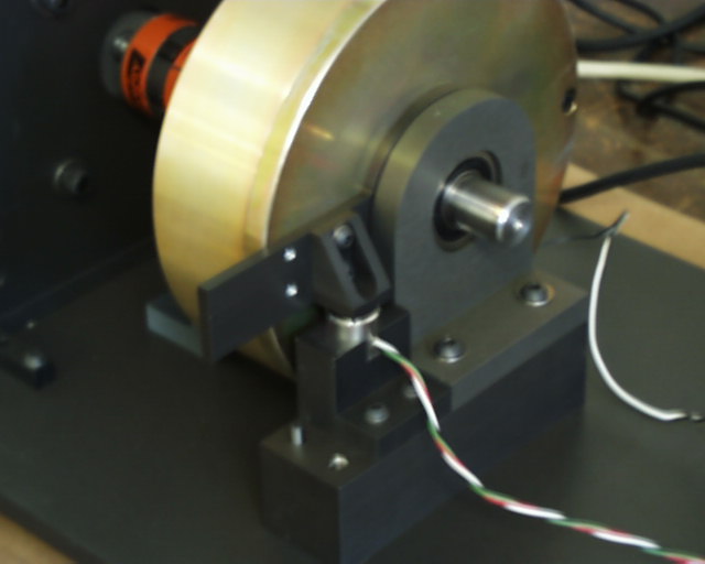
| Here is a picture of the load cell sitting in it's mounting block. This block can be mounted in two different positions in order to optimize the range of the load cell for different sized motors. The current position is best for smaller motors in the 1/4 to 1/2 hp range and the left position is best for 1/2 to 1 hp motors Set pins are used to precisely locate the load cell mounting block. |
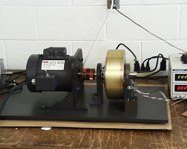
| Here is a picture of one of our set ups. The gold colored object is a Magnetic hysteresis brake that we purchased from Magtrol. On the left is a 1/3 hp AC inductive motor that will be used for tests. Not shown in this picture is a 1/3 hp DC PM motor with speed controller that will be used for comparison/show differences in characteristics between AC and DC motors. |
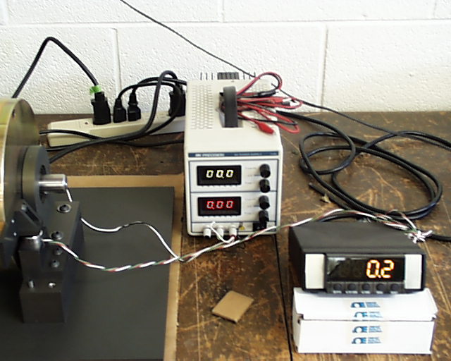
| Here is a picture of the power source for controlling the Magtrol brake, and the load cell panel meter mounted in a custom case that I built. The power source varies the voltage to the brake, which controls tha amount of load torque on the motor. We bought a generic electronics box and milled and drilled the appropriate holes and slots in the case and front/back aluminum panels in order to obtain a pretty compact, snug fit for the meter. On the back I put an outlet for a cord, an on/off switch, and a detachable connector for the cable leading to the load cell. I'll put up a picture of this in the future. |
 |
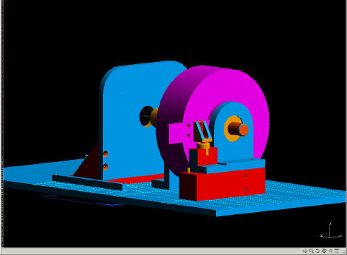 |
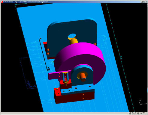
| This is a front view of the 3D solid model I created in order to design the dynamometer. |
| Here is a top view of the same model rendered using the I-Deas solid modeling package. |