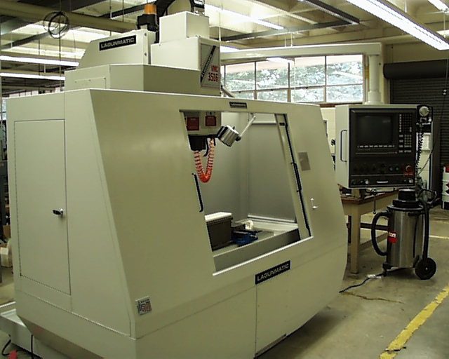
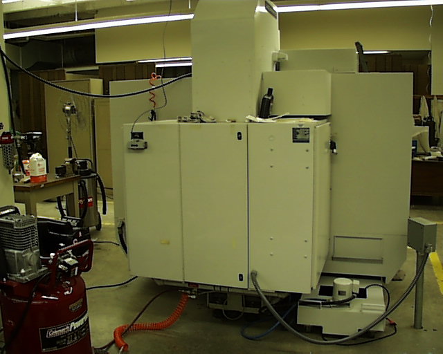
After the painting was finished, my next task was to get the mill operational. This mill uses compressed air in order to pressurize the scales(keeps contaminants out), and to run the tool magazine. Well, our shop air supply only goes up to about 80 psi and the tool magazine needs at least 100 psi to function properly. So we had to buy an air compressor that could deliver that much pressure. We got a 27 gallon tank that produced 120 psi to do the job. Originally everything ran on a single pneumatic circuit. However, I found that the pressurized scales leak air all the time(by design) and this was causing the compressor to cycle constantly in order to maintain the pressure needed to run the tool magazine. The tool magazine itself doesn't run very often and therefore doesn't use a lot of volume so it was decided to split the circuit up, running the scales off of central shop air and run the compressor only off of our dedicated air compressor. This solved the problem and the compressor cycles very seldom now and we still have the air volume for the scales and pressure required for the tool magazine. I next had to
teach myself how to run the mill. This was a little bit intimidating at first but was neccesary because no one else here knew how to run it. So I did A LOT of reading, and wrote a lot of little test programs in order to get familiar with the machine's capabilities. I kept my hand on the emergency stop a lot at first until I became confident that I knew what I was doing and wasn't going to cause a machine head crash or something disasterous like that. After a while I was able to use the mill to actually build parts that were needed for various projects. This was the fun part. One of the first things I did was to write a routine to mill the bolt hole pattern, shaft hole and mounting face pocket on the mounting plate for the dynamometer project. This was done first on a test piece of acrylic plexy glass in case I had any bugs in my routine. I was very pleased with the results when I did the cuts on the actual aluminum mounting plate. It turned out beautifully! My next task was to set up a communications link between the controller on the mill and a PC that we would have various CAD and CAM software installed such as I-Deas and MasterCam. This may sound like an easy task but in reality was an exercise in troubleshooting and problem solving. We ended up building a 50 ft. cable with serial port DIN connectors for this link. |