Glenn’s Treatise on a Preferred Color, or the Lack Thereof, of Fog Lights
For years, I was one of the many people who succumbed to the myth that fog lights are supposed to be yellow—all because I knew that Earth’s atmosphere scatters blue light better than that of longer wavelengths, thus explaining the blue sky and why the sun appears reddish at sunset. Never mind the fact that I was aware that fog droplets are a lot larger than air molecules and scatter differently. Never mind the fact that I’ve long had a “computational tool” with which to actually answer the question. I just made a “natural” generalization. Well, a couple of years back, when I first saw cars with those really pretty bluish-purple fog lights, I decided to actually use what I knew and answer the question. In case anyone else cares, and because I’m really bored evenings, I’ve documented my results here. (The conclusions here are not new. See, for example,
http://www.visualexpert.com/Resources/weather.html
or
http://www.lrc.rpi.edu/programs/transportation/pdf/PAL/PAL2001-bullough.pdf.)
First, the idea behind a preferred color is that it would give better visibility or penetration into the fog. “Penetration” relates to something known more technically as “extinction.” The process by which a beam of light becomes dimmer as it propagates through some medium is called “extinction.” (The medium extinguishes the light.) The less the extinction, the greater the “penetration.” The amount of extinction is quantified by an extinction coefficient. Call it “ALPHA”. If a beam of light has intensity I0 at one point, it will have intensity
I = I0 * EXP(-ALPHA * L)
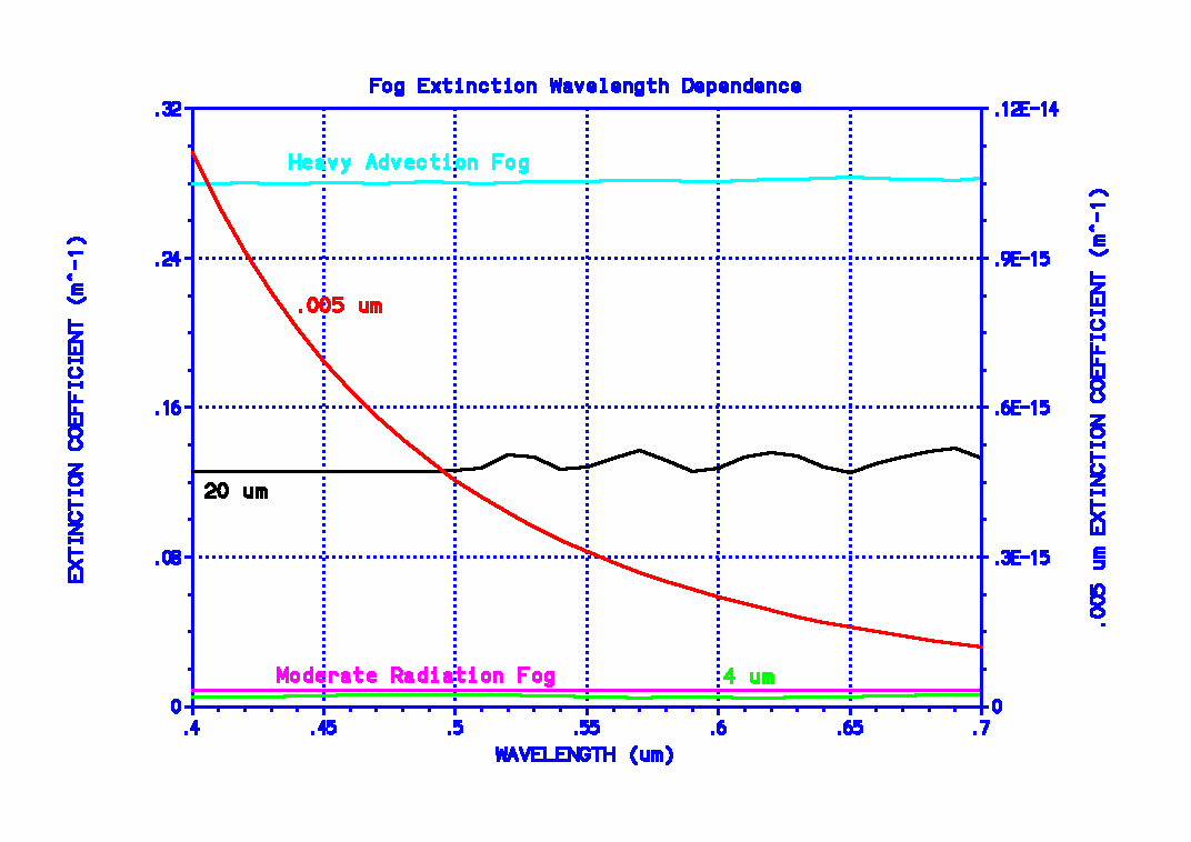
after travelling a distance L from that point. (“EXP(X)” refers to raising the natural number “e” to the X power. I will always be less than I0.) Note that ALPHA generally depends on the wavelength. (It should be clear that wavelength is the physical parameter that correlates with what we call “color.” Visible light has wavelengths from .4 (blue/violet) to .7 (red) um. (“um” means micrometer (or micron). The “u” is supposed to be the Greek letter mu, but I’m doing this without using “fancy word processor features.”) So, the fundamental idea here is that fog lights should be of a color that makes ALPHA significantly smaller than at other colors. For the case in which the wavelengths involved are all much larger than the particles causing the scattering, ALPHA decreases smoothly as wavelength increases. This is shown in the plot below. This plot shows the extinction coefficient (ALPHA) as a function of wavelength for water drops of various sizes or various distributions of sizes. Consider the curve labelled “.005 um”, and use the scale on the right of the plot if you actually want to read values from this curve. This curve gives ALPHA for the case in which there are 200 drops per cm^3, all of .005 um diameter. This diameter is much smaller than any of the wavelengths our eyes are sensitive to and ALPHA does indeed decrease smoothly as wavelength increases. (Atmospheric molecules, which are of course even smaller, would show a curve that decreases in the same basic way.) The question arises that, if the “.005 um” curve was in fact descriptive of fog, why not use red light instead of yellow? After all, ALPHA is even smaller at .7 um than at .575 um (roughly where “yellow” is in the spectrum). All I’ve ever been able to come up with is that the human eye is generally more sensitive to yellow light than red and so it doesn’t make much sense to optimize lighting with wavelengths we don’t detect all that well.

The ultimate problem with using the “.005 um” curve as a guide to designing fog lights is that fog is composed primarily of droplets much larger than .005 um. Fog in fact contains a distribution of droplet sizes. The exact sizes involved, and the maximum diameters encountered, depend on the particular fog. Particles with sizes near or larger than the wavelength scatter light much differently than do very small particles. Small particles tend to scatter unpolarized light (e.g., the kind of light emitted by headlights and fog lights) more or less equally in all directions. Larger particles don’t scatter light so uniformly. (They tend to scatter light more into the forward hemisphere, i.e., in the general direction that the light was already heading. Strangely, the physics of what causes this actually decreases the beam intensity.) The following diagram shows the unpolarized scattering pattern of a very small water drop and that of a typical fog droplet. There simply is very little or no similarity between the two patterns. An air molecule scatters visible light (and longer wavelengths) with the same basic pattern as that of the small water drop in the diagram. (The patterns are relative. No implication is intended that a small water drop actually scatters as much into the forward direction as a fog drop or that the backscattering from a fog drop is actually less than that from a very small water drop. The backscattering from a fog drop is just much less than forward scattering.) This diagram should make it clear that whatever benefits yellow fog lights might have, they have absolutely nothing to do with what happens with sunlight and air molecules in the atmosphere.

The following plot shows two different models of the size distribution of fog droplets. (Size distributions that consist of non-constant particle sizes are called “polydispersions.” A distribution of constant-sized particles would be a “monodispersion.”) Do not get hung up on the difference between “advection fogs” and “radiation fogs.” You may have enough trouble figuring out how to interpret the curves, especially if you think about those strange units on the vertical scale. “per cm^3 per um”, what’s that? Don’t get hung up on that either. The really important point is that, as mentioned before, fog is composed of a whole bunch of different sized droplets. The fog examples shown here are most dense for drop radii of 10 or 2 um. But if you really want to understand those units on the vertical scale, okay, here goes how to interpret those curves. The curves represent density functions. But they don’t just give the drop density as a function of drop radius. There’s a double meaning behind the term “density function” here. They give the drop density per increment of drop size (radius). Let “dr” be a small interval of radius and “r” symbolize the radius. Symbolize either curve as the mathematical function “n(r)”. The way you would interpret a curve in this figure is to say that, for any given value of r, there are n(r)dr drops per cm^3 with radii between r and r + dr. More technically, dr is an “infinitesimal” quantity. The number of drops in a cubic centimeter with radii between r1 and r2 is given by integrating n(r)dr from r1 to r2. The total number of drops per cm^3 irrespective of size is given by integrating n(r)dr over all values of r (theoretically, r1 = 0 and r2 = infinity). For both curves, that all-encompassing integral gives N = 200 drops / cm^3 for the total density (the same value used to generate the “.005 um” extinction coefficient curve in the first figure).

Okay, with that digression out of the way, we can continue. Before considering all drop sizes at once, just consider a distribution of drops of diameter 20 um (where the advection fog curve maximizes). The curve labelled “20 um” in the first figure gives the extinction coefficient for this large drop size (with 200 drops / cm^2). As with all curves in that figure other than the “.005 um” one, use the vertical scale on the left. That curve in no way decreases smoothly as wavelength increases. It oscillates somewhat and very gradually increases with increasing wavelength (but not enough to make blue fog lights a particularly good idea). There is no clear preferred color for fog lights indicated there. The radiation fog drop size distribution maximizes at a diameter of 4 um. Even with this much smaller size the “4 um” curve in the extinction coefficient plot doesn’t show any particular preferred color for fog lights. The extinction coefficient is again virtually independent of wavelength.
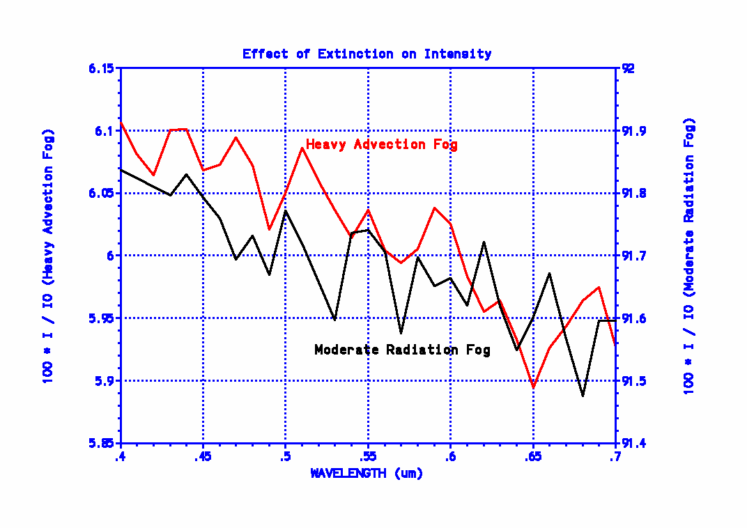
Just to counter any arguments that this lack of a preferred color is being caused by assuming a monodispersion and that considering the full distribution of drop sizes might show something different, the initial extinction coefficient plot also shows ALPHA for the two polydispersions of the second plot (showing the size distribution functions). The oscillations of the “20 um” plot are greatly reduced in the “heavy advection fog” curve. Both it and the “moderate radiation fog” curve again show essentially no dependence on wavelength. Just to show the extinction behavior’s dependence with wavelength perhaps more explicitly, the following figure plots 100 * I / I0 (the percentage transmittance) from the above equation as a function of wavelength, for L = 10 m, using the extinction coefficient functions for the two polydispersive fog curves of the first plot. Because of the greatly expanded vertical scales, the slight oscillatory nature of the curves is shown. (Note that this same basic oscillatory behavior would’ve been seen in the first plot if a different vertical scale had been used.) In the figure below, again note that the lefthand vertical axis is used for one curve and the righthand vertical scale is used for the other. Again, looking at the average behavior with wavelength and ignoring the insignificant oscillations (remember that greatly expanded scales are used), if there is any systematic trend in this figure, it favors fog light colors corresponding to short wavelengths (blue or violet), not longer ones (yellow or red).

It might be noted that if some particular fog was composed of drops small enough for the phenomenon described by the “.005 um” extinction coefficient curve to apply (it’s called “Rayleigh scattering,” by the way), from the actual values of the extinction coefficients, it should be apparent that the extinction is so low even for blue light, that there would be no need to worry about the optimum color to use! As a final note on the alleged advantage of yellow light in regard to penetrability, if there was any significant preference for the shorter wavelengths to be scattered out of the beam, white headlights on oncoming cars would appear reddish (not, in fact, yellow), just as the setting sun sometimes appears reddish. I’ve never observed such an effect. (All I see is white.)
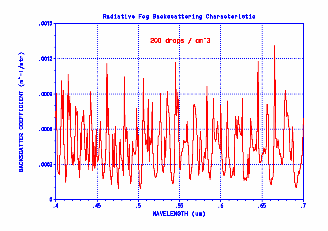
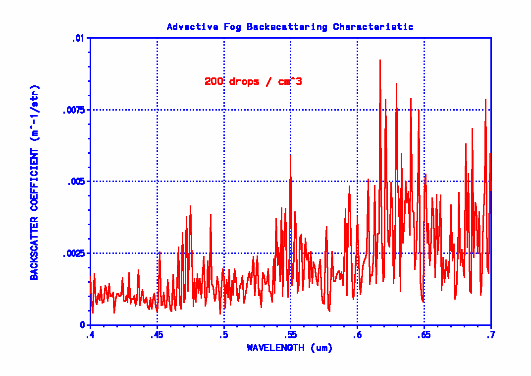
Now then, I’ve come across a particularly bizarre reason cited for preferring yellow light. The claim is made that it has nothing to do with penetrability but that yellow light backscatters less and thus doesn’t cause the “blinding effect” of (white) headlights. The following plots show the backscatter coefficient for a radiative and advective fog as functions of wavelength. No preference for yellow is shown here. If there’s any preference for any specific color, it’s in the advective fog plot—but in the reverse direction. It seems to show a slight overall increase in backscattering as wavelength increases! (As if that trend was significant (it isn’t), if you’re driving near water, maybe you should use blue fog lights.) But this in its entirety begs the question! Just for the sake of argument, pretend either figure does show some preference for yellow light. So what? We aren’t talking about replacing (white) headlights with yellow ones (of the same power output). If turning on fog lights doesn’t improve visibility of what’s ahead of you in the fog by using a wavelength that penetrates to that object and back better than what your headlights are already doing, why turn them on in the first place? How is the backscatter behavior relevant?

