
 F-16 Integrated Avionics Test
Station (INATS)
F-16 Integrated Avionics Test
Station (INATS)
The INATS consists of a full-scale cockpit with a throttle,
side stick controller, displays, flight-worthy avionic spread bench, signal
conversion and access racks, head-up and head-down displays. Additionally,
it has visual display systems, an engineering work station and an automated
data processing system. Avionics installed for the F-16 Blocks 30, 40 and
50 systems includes:
- General avionics/enhanced fire control
computer
- Data entry/enhanced expanded electronics
unit
- Enhanced central interface unit/advanced
central interface unit
- Programmable/expanded display interface
unit
- Multifunction display set
- Up front controls, integrated control panel,
data entry display, and pilot's fault list display
- Stores remote interface units
- A, B, C, D and W MUX buses
In addition to a scientific and engineering staff, F-16 avionics suites
and standard laboratory equipment, the INATS has the following:
- Four VAX 11/785 minicomputers with an MA
780 shared memory
- One VAX 11/780 and VAXSERVER 3500 and two
IRIS 3110 encoder/displays
- Three DTI and PAX multiplex bus terminals
for MIL-STD-1553 bus recording and simulation
- One Fairchild bus monitor with remote terminal
capabilities
- Three video monitors/recorders, a signal
recording system & three Silicon Graphics systems
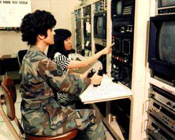
F-16 Radar Test System (RTS)
The RTS consists of a set of radar LRUs. The LRUs are in
a holding fixture, test bench, EW signal generator, target generator, an
automated data processing and instrumentation system, a MIL-STD-1553 bus
simulator, cockpit controls and displays and aircraft avionics that include
a general avionics computer (GAC) and a programmable display generator.
In addition to a scientific and engineering and standard RF test equipment,
the RTS has:
- MicroVAX minicomputer
- Stripchart recorder
- Data acquisition instrumentation systems
- Westinghouse swing buffer with a high-speed
tape recorder
- Video monitors and recorders
- Test target generator
- Ground-based jammers
- UHF communications
F-16 IFAST test bays provide avionic/EC ground test support to the F-16
CTF for Block 30, 40, and 50. Additional customer support includes Hill
AFB F-16 Block 30 for SCU-2, Los Alamos Naval Laboratory for radar simulation,
LANTIRN integration, Seek Eagle program, contractor test programs and foreign
military sales.
POINT OF CONTACT (F-16 INATS & F-16 RTS)
Chief, F-16 Integrated Systems
Test Branch
20 Hoglan Avenue
412 TW/EWWI
Edwards AFB, CA 93524-8170
Voice: (661) 555-6984, DSN 555-6984 FAX:
(661) 555-3461, DSN 555-3461
Secure Phone: (661) 555-0842, DSN 555-0842 Secure
FAX: (661) 555-3492, DSN 555-3492
F-15 Avionics System Integration
and Test Laboratory
Our technicians extensively test new radar Operational Flight Programs
(OFPs) using the APG-70 Radar Test Bench (RTB). The APG-70 RTB interfaces
with the F-15E tactical avionic systems including the Central Computer,
Inertial Navigation System (INS), Crew Station Controls and Displays and
Interrogator Reply Evaluator (IRE). We conduct postflight RTB tests for
analysis of anomalies from flight tests. We also accomplish radar OFP ground
testing using various methods to simulate targets.
Interactive Data Reduction and Analysis System (IDRAS):
We use the IDRAS for the reduction and analysis of APG-70 radar flight
test data. Upon completion of an F-15E radar flight test, we transfer the
onboard 28-track magnetic tape with flight test data from the aircraft
to the F-15 IFAST bay. Our technicians reduce the 28-track data are to
9-track format. They normally accomplish extensive analysis on the test
data. Additionally, they also use IDRAS to collect test data from APG-70
radar testing accomplished at IFAST.
F-15 Avionics Integration Support:
The F-15 has a total of 7 software controlled avionic systems. These include
the Central Computer, Multipurpose Display Processor, Avionics Interface
Unit, Radar, INS, Programmable Armament Control System and Flight Control
System. We operate or simulate ninety percent of the F-15E avionics in
the F-15 IFAST test bay. Our technicians periodically develop new software
reflecting system improvements and release it for flight test and subsequent
installation in the operational fleet. The technicians verify any hardware
or software discrepancy detected in any flight test on the integrated avionics
test benches in IFAST. Subsequent fixes are verified prior to reflights.
The integrated avionics test benches also provide a valuable training tool
for pilots, weapon system operators and engineers; particularly for new
OFPs.
Avionics Intermediate Shop (AIS):
AIS capability utilizes the F-15E avionics test benches, which affords
a "hot mock-up" environment. Avionics engineers install suspected
defective LRUs on the test benches and monitor their operation. They conduct
fault isolation to an internal board level using traditional troubleshooting
techniques. We return any LRUs identified as defective to the appropriate
AF shop for disposition. We return serviceable LRUs to the CTF for aircraft
installation. The AIS test benches provide software reload capability for
all of the microprocessor driven avionic systems in F-15 aircraft.
ECM Pod Preflight Testing:
The F-15 fire control radar is designed to be effective in an ECM environment.
The dynamic nature of ECM combined with new tactical radar modes necessitates
software changes to the ECCM capabilities of the radar. Our technicians
use the ECM pods mounted on support aircraft to exercise the ECCM capabilities
of the F-15 radar during flight tests. We accomplish pre-takeoff testing
of ECM pods on support aircraft from IFAST to ensure optimum results during
flight.
POINT OF CONTACT
Deputy for Engineering Chief,
Radar Test
445th Flight Test Squadron/ENR
95 North Flight Line Road
Edwards AFB, CA 93524-6020
Voice: (661) 555-6466, DSN 555-6466 (661) 555-9897, DSN 555-9897
B-lB Offensive Avionics Laboratory
(OAL)
The Vehicle System Simulator (VSS) emulates the air vehicle systems
as required to operate the offensive avionics through a simulated flight
profile. The crew member can execute and pre-fly test procedures in the
OAL environment prior to flight tests. The Weapons System Simulator (WSS)
emulates the weapons intended for use on the B-lB. We use one channel of
the offensive radar system to operate and test in the OAL. Using available
facilities in IFAST, we accomplish ground testing of the B-lB radar. Additionally,
a Radar System Simulator (RSS) provides capability for the aircrew to interact
with the radar set. The B-lB defensive avionic system and OAS are integrated;
however, we can operate each independently. The OAS contains crew station
controls and displays for both offensive and defensive avionic systems.
Radio frequency (RF) management between the two systems is an important
integration requirement evaluated in IFAST.
The Integrated Test Station (ITS) provides the capability to integrate
weapons with core avionics. Technicians perform weapons integration testing
prior to aircraft installation. This may be the first occasion for a weapon
to be fully integrated and tested with B-lB core avionics. The ITS provides
a means for replication and investigation of anomalies experienced during
flight. Our technicians use the ITS to investigate hardware and software
anomalies and record activities on a variety of data recording systems
to facilitate real-time data analysis as well as post-test analysis.
The Test Mission Data Preparation System (TMDPS) is in the B-lB IFAST
test bay. It provides the capability to produce mission data and avionics
flight software data transfer unit cartridges (DTUCs). Technicians generate
mission data DTUCs prior to flight. The DTUCs contain flight profiles,
sequence or way points and target information. They also store information
required by the Avionics Flight Software (AFS). The dynamic requirements
of flight test often demand short-notice changes to the planned test flight.
The OAL supports software changes on-site due to the flexible capability
of the DTUCs. We also use DTUCs during aircrew training by providing point-to-point
simulation runs of the planned test profile. Technicians subsequently install
a DTUC on the B-1B aircraft for test flights. AFS DTUCs are built from
9-track tapes in support of the test program. The TMDPS provides on-site
capability to produce AFS and mission data DTUCs to support test flights
and crew training. The B-lB OAL possesses test sets required to bench test
all avionic LRUs. Additionally, we accomplish LRU modifications and intermediate
level maintenance in the B-lB IFAST test bay.
B-lB Defensive System Laboratory
The B-lB Defensive Systems Laboratory consists of the following:
a single sector and core avionics of the defensive avionic system as installed
on the B-lB aircraft, LRU STE stations, dynamic signal generator, engineering
work stations and VAX computers for data reduction, data analysis and real-time
analysis of the defensive avionic system. Systems integration capability
provides a unique test environment in which to test the B-lB Defensive
Management System.
In addition to the engineering staff, the defensive avionic systems
test station, the LRU specialized test equipment (STE) and standard lab
equipment, the defensive laboratory has the following resources:
- VAX 8530 & 11/750 computers with MIL-STD-1553
data bus interface
- Digital MIL-STD-1553 data bus recording
and simulation
- Multiple SBA-100 MIL-STD-1553 data bus
analyzers
- Video monitors and recorders with full
editing capability.
POINT OF CONTACT (B-lB OFFENSIVE AND DEFENSIVE SYSTEMS)
Chief, DT&E 419th Flight
Test Squadron
300 North Wolfe Avenue
Edwards AFB, CA 93524-6075
Voice: (661) 555-0656, DSN 555-0656
F-16 Integrated Avionics
Test Station II (INATS II)
INATS II consists of a full-scale F-16 cockpit with controls and displays,
flight controls, avionic spread bench, LRU data interface panel, simulated
and/or real head-up and head-down displays, Defense Mapping Agency (DMA)
Digital Terrain Data, visual scenes with air-to-air and air-to-ground targets
and video recording for all cockpit displays. Additionally, the GTS combines
the attributes of a highly realistic mission simulator with the test capabilities
of an avionics hot bench. Utilizing the latest in low-cost visual simulation,
instrumentation buses, high-speed networks and open architecture hardware/software,
the GTS provides extensive and flexible capabilities for low cost avionic
systems development and testing. We base this on the following distributed
resources:
- Simulation Executive. Four CPU Silicon
Graphics IRIS/4D Skywriter systems to run avionic models, graphics, calculations,
and networking (each on a separate CPU).
- Simulation Control. User will be able to
control the simulation as a background task run on a Silicon Graphics 4D/440
using X-Windows MOTIF format structure.
- Graphics (OTW display and crew station
displays).
-- OTW scene
using three-dimensional textured configurable display.
-- Cockpit
simulation for analog cockpit instruments and displays or simulation MFDs.
-- Cockpit
simulations for modeled functions: ie radar, target pods, air-to-ground/air-to-air
munitions, etc.
- Avionic models.
-- Avionic
models run in the foreground (executed every major time frame cycle), interfacing
to simulation via shared memory.
-- Models consist
of separate input/output (I/O), decision and computational sections to
allow for reconfigurability of modeled avionics with real avionic hardware
and software.
- Data Collection.
-- Five MIL-STD-1553
data buses may be monitored simultaneously plus one MIL-STD-194 data bus.
-- MIL-STD-1760
weapons interface.
-- User programmable
display format and scaling.
-- Triggering,
filtering, event definition, and calculation will be available.
- Other GTS attributes.
-- Reconfigurable
for different aircraft crew stations, controls, displays, LRUs, software,
etc.
-- High-speed
network consisting of 1.5 gigabytes/second serial fiber-optic reflective
memory interface connecting GTS components (executive, cockpit l/O and
data collection).
-- Cockpit
l/O utilizing a VME bus chassis and digital/analog signal processing and
conditioning.
-- Low speed network
for non-real-time GTS tasks (simulation control during log-ins, development
workstations during maintenance). Ethernet utilized for network interfacing.
POINT OF CONTACT (GENERIC TEST STATION)
Chief, Integrated Systems Test
Branch
20 Hoglan Avenue
412 TW/EWWI
Edwards AFB, CA 93524-8170
Voice: (661) 555-6984, DSN 555-6984 FAX: (661)
555-3461, DSN 555-3461
Return to top
|