

GC_ET_AP_Ckt_B.html
2021-01-13 21:58:32 2026-07-08 08:05:36
*** Right-Click Schematics and Plots for larger image ***
******* Simple Developmental ckt , proof of concept.
***********************************************************************
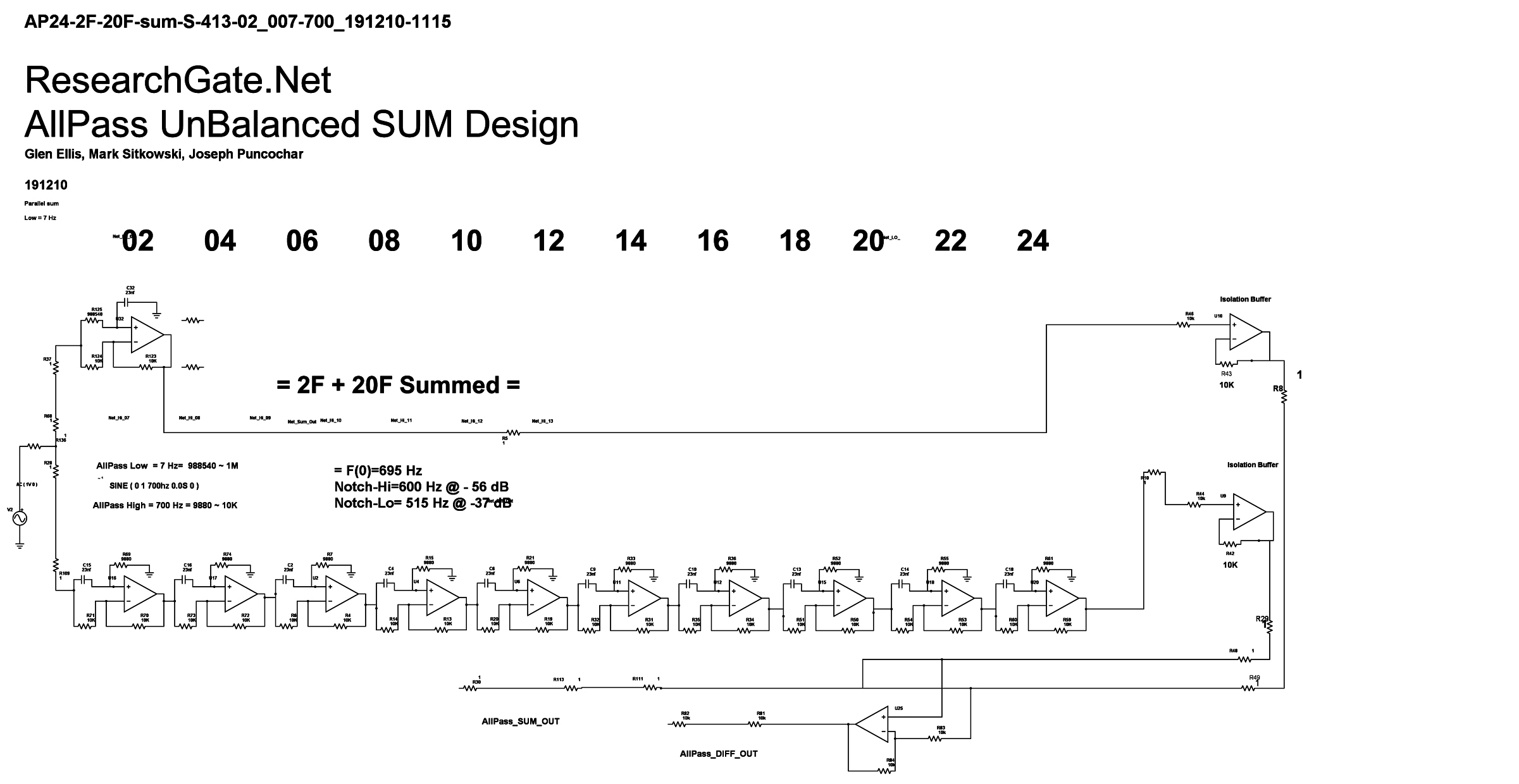
### Below is the Revised and Simplified All-Pass Schematic
### with ONE APF-Lo=7Hz and TEN APF-Hi=700Hz.
*** Below is the Revised All-Pass Bode Plot for All-Pass V(out)
*** showing Notches where w=0 or w=pi.
*** The tick indicates f(700).
*** The two adjacent notches [ f(515) and f(900) ]
*** are exactly useful for building a Working Band-Pass Filter.
*** Below is the Revised All-Pass Bode Plot for All-Pass V(out)
*** showing Notches where w=0 or w=pi.
*** The tick indicates f(700).
*** The two adjacent notches [ f(515) and f(900) ]
*** are exactly useful for building a Working Band-Pass Filter. 
*************************************************************************************************************************************************
*************************************************************************************************************************************************
*************************************************************************************************************************************************
*** In this All-Pass project,
*** the authors accidentally tuned all the All-Pass-filter stages
to f(0) = 7 Hz and to f(0) = 700 Hz ,
*** which accentuates the "w" notches at each "0" and each "pi" point in the spectrum.
*
*** Observing the useful Bode plots, we explored further, along this Accidental Path.
*** In the fully developed #1 Working Circuit,
*** we preceeded and followed the All-Pass array
*** with Multi-FeedBack Band-Pass OpAmp Active Filters
*** to reduce unwanted side-band signals ( away from f(0) = 700 Hz ).
*** The authors explored the "UnBalanced" ([1F & 10F] and [7 Hz & 700 Hz] ) approach.
*** The All-Pass-Lo is tuned to 6.92 Hz (7Hz).
*** The All-Pass-Hi is tuned to 692 Hz (700Hz).
*** These frequencies were chosen to utilize standard resistor values.
*** Presented above is a Simplified Proof-of-Concept All-Pass Filter
*** showing the array of notches,
*** two of which are +/- f(700) and exactly useful.
*****************************************************