 |
|
|
|
|
|
|
|
|
|
|
|
|
|
|
|
|
|
|
|
|
|
|
|
|
|
|
|
|
|
|
|
|
|
|
PLEASE READ THE ENTIRE INSTRUCTIONS BEFORE BEGINNING! |
|
|
DIFFICULTY LEVEL FOR A NOVICE = (7 TO 8) on a scale in which 10 is the most diffcult.
A "NOVICE" for these purposes is defined as someone who has little or no electronic repair training, skills, knowledge, tools or qualified mentor to provide guidence. |
|
|
FLASHING CODE 51: This code indicates a potential and/or intermittent short to ground occured or exists in the SRS system. You must eliminate any short or intermittent short to ground prior to installing a new or properly functioning SRS Computer Module. |
|
|
TOOLS REQUIRED:
"PATIENCE" -- (The bigger you are the more patience you'll need, I'm 6', 250lbs so I know)
"GOOD EYE SIGHT" -- (Especially for those close-up soldering operations on the PCB)
"KNEE PADS" -- (That is unless you have a hoist, steel knees or weight less than 100lbs)
"SOLDERING SKILLS" --(Welding skills DO NOT qualify)
Battery Disconnecting Tools -- 1/2" or 9/16" wrench usually, but I haven't a clue on your vehicle.
Ratchet -- 1/4" or 1/2" your choice OR Nut Driver Set
Socket -- 9/32" OR Nut Driver Set
TORX Drive -- #T-30 for your ratchet and/or TORX style Nut Driver Set
Screw Driver -- Small pocket style flat blade and/or jewelers screw driver set.
Soldering Iron -- 35 Watt MAX, with small 1/8" tapered tip (higher wattage will destroy the new TCO)
De-Soldering Tools -- or simple de-soldering wicking will do.
Heat Sink Transfer Clip -- small size or other method to divert heat away from the new TCO.
Solder -- Small gauge, .050", rosin core for electronic service, NOT Plumbing or Jewelry type.
Static Electricity Control Tools -- If you are un-familiar with these tools and proceedures, I stongly encourage you to become familiar before proceeding. |
|
|
PARTS REQUIRED:
1 - THERMAL FUSE, "THERMAL CUT-OFF (TCO)" NTE part number 8167 or NTE8167 or equivalent. |
|
|
STEP #1: DISCONNECT THE BATTERY FOR AT LEAST ONE HOUR BEFORE BEGINNING!
(FAILURE TO DO THIS MAY RESULT IN AN UNEXPECTED AIR BAG DEPLOYMENT! |
|
|
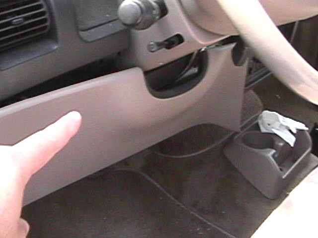
STEP #2: Remove the three (3) small 9/32" head screws from the bottom of the "interior colored" plastic cover panel, located under the steering column. (The top part is held into place by blind clips, so simply give a gentle pull at the top edges once the three (3) 9/32" head screws have been removed) see photo #1 below. |
|
|
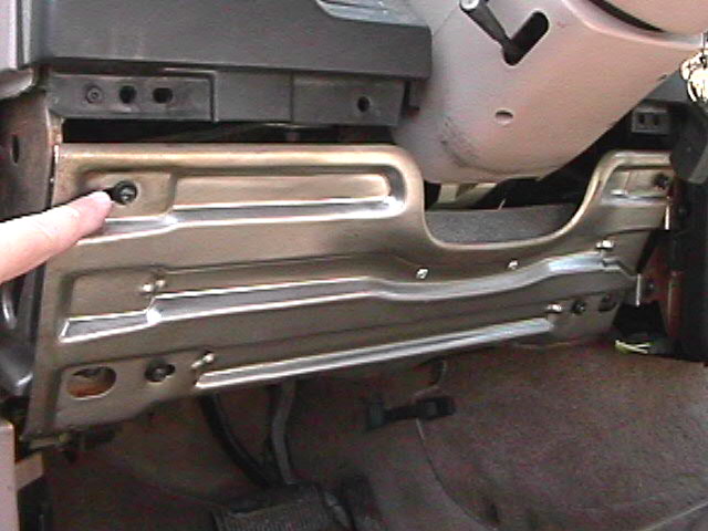
STEP #3: Now remove the four (4) T-30 size TORX head bolts, which are securing the inner steel brace panel to the dash bulhead structure. (Look closely, as there are other TORX head bolts visible that you do not want to remove) see photo #2 below. |
|
|
 |
|
 |
|
|
AEROSTAR SRS LOCATION/SERVICE (STEP #2) PHOTO #1 |
|
|
|
|
AEROSTAR SRS LOCATION/SERVICE (STEP #3) PHOTO #2 |
|
|
|
|
 |
|
|
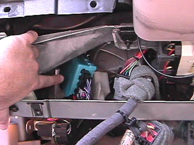
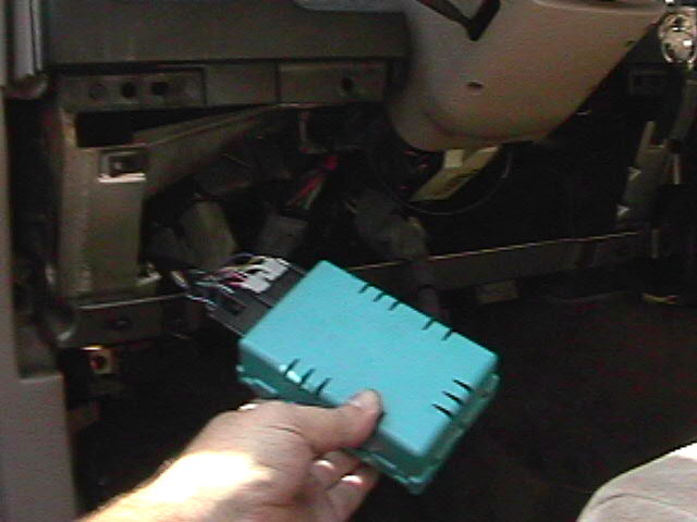
STEP #4: Now you have a clear view & access to the area, find the "Robyn's Egg Blue" colored SRS control box to the left of the steering column as shown in photo #3 below. Check to see if any zip/wire ties are securing the control box. If so, remove them, otherwise the control box should only be held into place by its attaching spring loaded slide clip from above/ right of the control box. Firmly grip the contol box & give a gentle pull straight down towards the floorboard, it should come off the clip. If not, use a small screwdriver to assist the spring clip in releasing the control box tab. If force is used, damage could occur to the control box, printed circuit board (PCB) or wiring harness. Once the control box is removed from the dash bulkhead, carefully fish it outside the dash area as shown in photo #4 below. Then carefully disconnect the two (2) wire harness connectors from the SRS control box. Be careful not to cut or damage the wiring harness on the sharp edges of the lower metal dash support brace. |
|
|
 |
|
 |
|
|
AEROSTAR SRS LOCATION/SERVICE (STEP #4) PHOTO #3 |
|
AEROSTAR SRS LOCATION/SERVICE (STEP #4) PHOTO #4 |
|
|
|
|
|
|
|
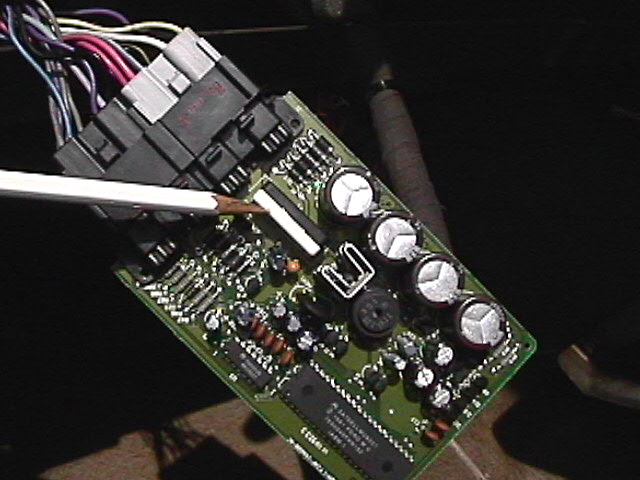
STEP #5: CAUTION;(Components on this control PCB are sensitive to static electricity and can be damaged or destroyed if proper precautions are not followed). At this point you should have the control box completely removed from the vehicle. Looking closely, you will see that the blue box is two halves snapped together. Place the deep half of the box down on a table, take a small flat blade screwdriver and gently unclip the box apart. The PCB is loosely sandwiched between the two halves and will fall out, once the two halves are apart. Handling the PCB properly to avoid any static transfer, look for a black & white, aproximately 1" long by 1/2" wide, plastic component housing, located closest to the connector end of the PCB as shown in photo #5 below.
STEP #6: The black/white plastic box is similarly held together as was the blue box. Using a small flat blade screwdriver, carefully pry open the black/white box as shown in photo #6 below. You will now see the Thermal Fuse (TCO) to be replaced. There is a smaller black resistor below/under the TCO. Replace only the TCO, normally the resistor is fine and does not need replacement. De-solder the old TCO only and remove all residual solder from holes. |
|
|
 |
|
 |
|
|
TCO housing location on the PCB
(STEP #5) PHOTO #5 |
|
The TCO inside the B/W box, Note the position! (STEP #6) PHOTO #6 |
|
|
|
|
|
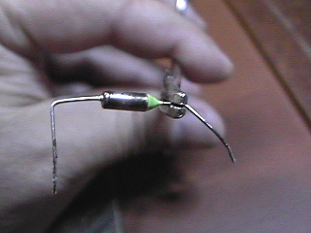
STEP #7: Depending on the manufacturer of the TCO, the physical size may be slightly larger. It will still fit inside the B/W housings as shown in photos 5 & 6. The lead legs might also be larger in diameter, but should fit into the PCB holes "IF" you remove ALL solder from around the hole when the old TCO is removed. Note the specific position of the TCO as noted in photo #6. The lead leg on the tapered epoxy end of the TCO must go into the PCB hole closest to the connector end of the PCB. Using a small needle nose type tool to hold, measure & bend the lead legs for the proper overall spacing to fit both the B/W housing & the PCB holes. Do not cut any lenght off until after soldering is completed. See the 2 photos below. |
|
|
|
Once the new TCO is fitted properly, position it inside the black half and back into position above the resistor. Use heat sink clips on the TCO leads during resolding to keep heat from damaging the new TCO. Reassemble the B/W halves, PCB into the blue box, with the battery disconnected, reconnect & Close the operation. |
|
 |
|
|
 |
|