Well, here she is:) This is a jet turbine engine that I built myself in a stretch of about 3 weeks. It utilizes a Cummins 3032068 turbocharger as the turbine and compressor section, and a combustion section of my own design. The fuel (diesel) is supplied by a home oil fueled furnance fuel pump, and discharges through a 1.1 gallon per hour home heating nozzle to start, and the engine is then switched over to a vaporization system consisting of a piece of 1/4" brake tubing in the combustor that the fuel passes through and is vaporized from the heat generated by combustion. The engine is started by a nozzle that blows directly onto the compressor wheel to spin it up to a usable level of boost. The spark is then turned on, followed by the fuel and hopefully within a few seconds, the engine fires up:) The oil system is a 1/4 HP motor that spins a coolant pump from a bandsaw, which delivers Valvoline 5w-30 oil at 40 PSI to the turbocharger's bearings. The engine is currently dependent on 120 VAC, but the plans are to later convert it to either 12 VDC or a small gasoline motor for running the fuel and oil pumps. The engine has been succesfully run up to 20 pounds of boost pressure, at an estimated 65,000 RPM, which is considered to be full throttle. The engine lacks a nozzle as of now, but thrust estimates with a nozzle put it in the neighborhood of 50 pounds of thrust at full throttle, which puts it in the 90 shaft horsepower class. Fuel consumption has not been evaluated, but I estimate it at approximately 10 gallons per hour. This turbine engine has been named "Intimidator" in honor of Dale Earnhardt, NASCAR's greatest driver, who lost his life in a last lap crash in the 2001 Daytona 500. The name fits the engine well, as it is honestly the most scary creation I have ever built.
Pictures
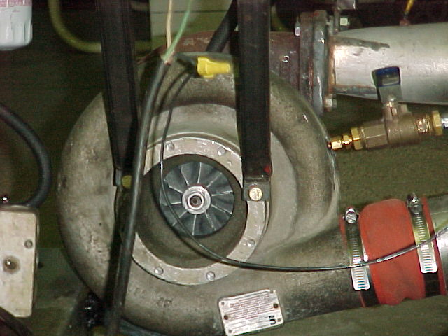
Here is a picture of the front of the engine,
looking into the compressor.
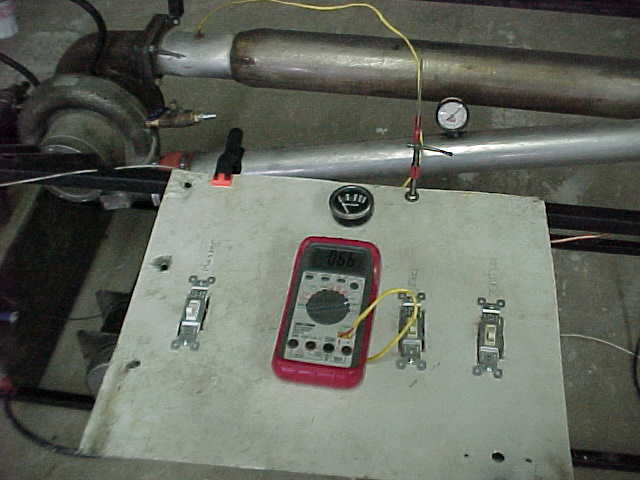
Current control panel. A bit of a hack job,
mainly just to get the controls placed right.
A picture of the oil pump and fuel/oil tank.
Black vertical streak marks the weld where the divider is to
seperate the fuel and oil. Tank was designed this way to
hopefully allow the fuel to cool the oil somewhat, but the design
has not been given a fair test yet to determine effectiveness.
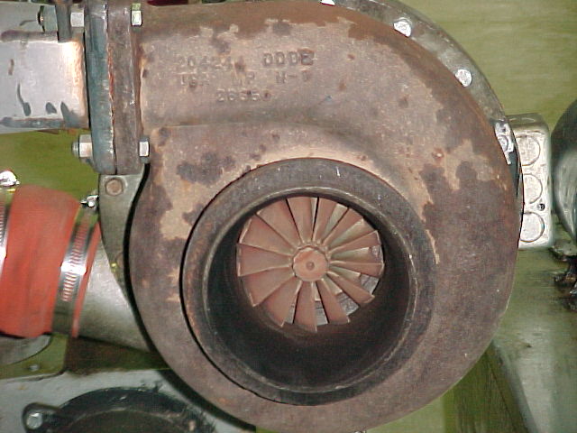
View looking into the exhaust side at the
turbine blades.
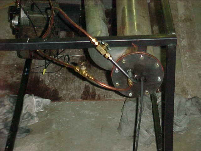
Here is a picture of the valves that control
fuel flow. Starter nozzle has an on/off switch located on the
bottom line, and main fuel supply is controlled by needle valve
on top line.
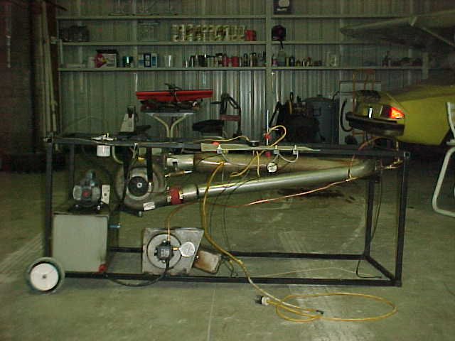
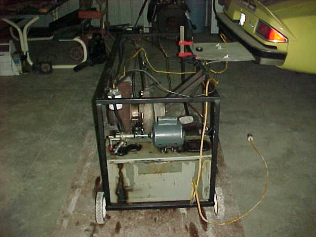
Here is an image of the turbine in it's stand
looking at the compressor side.
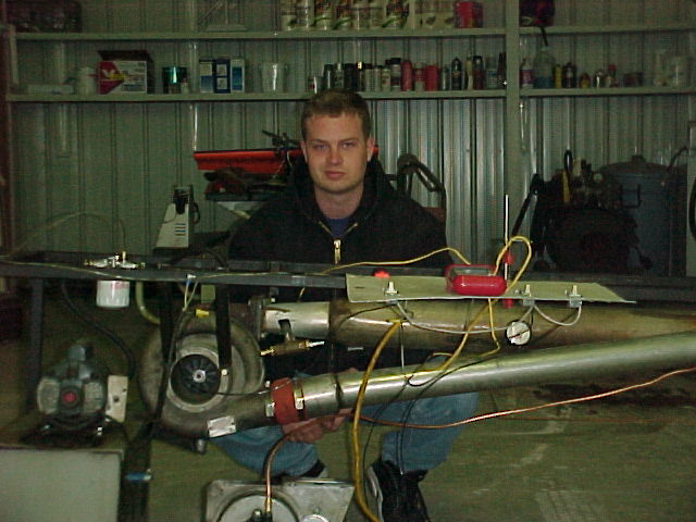
One last picture showing the turbine in it's
stand. Unfortunately, the photographer also caught the builder
doing what he does best. Looking grumpy:)
Sound file of jet running. Poor, but it's all I have so far.intimidator.mp3
If you would like to send me email about
this engine, my email address is:
[email protected]