

First we'll get rid of the "noise gate" effect. Let's
investigate how it happens. Everything shown here will be
measurements on the actual circuit, not simulations.
I'm using germanium AC128's, one with gain=157 (input stage),
other with gain=165 (output stage). Got the schematic at GEO,
where there's a great
article about the FF. I strongly
suggest you read it, in case you haven't already. Here is what I
measured with a DMM:
Q1 (input) |
Q2 (output) |
|
| Collector | -0.113 V |
-8.0 V |
| Base | -0.053 V |
-0.113 V |
| Emitter | 0 V |
-0.093 V |
We can note a few things. First, the Vbe drops are much less than one would expect. Second, Q2 is definitely at cutoff. Let's apply some signal (a sine wave) and see what happens. Ah, the "drive" knob is at maximum setting. Here is a oscilloscope shot of the collector of Q1 (I used Oszi for windows - it turns a PC with a sound card into a storage scope).
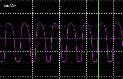
We can see that the top part of the wave form soon gets
"rounded" or "smashed", and as amplitude is
increased, the bottom part is clipped. The input of the sound
card is AC coupled, so I can't show where in the picture is the
point equivalent to the zero crossing of the input. Now let's
look at the collector of Q2:
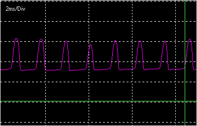
What we have here is highly asymmetric distortion. Q2 remains at
cutoff for until the voltage at Q1's collector is high enough to
bias it. The effect is that the wave is half-wave rectified.
Also, when Q2 begins to conduct, the impedance seen by Q1's
collector drops, what explains the "smashing" of the
top of the wave seen at the previous picture. Now what happens as
the input level is reduced (such when a note is dying or when we
turn the volume knob down)?
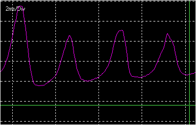
We can see two things. First, the signal NEVER gets clean because
more than half of the cycle doesn't pass through (it is
rectified). Also, there is a minimum level below it no signal
will pass, because Q2 won't get biased. Here is our "noise
gate". With a guitar plugged in, it sounds like this:
1) The initial attack of the notes is lost (until Q2 is put into
work);
2) Sustain part of the note have a harsh distortion, because the
exaggerated asymmetry generates too much harmonics;
3) If we turn the volume down, the not never gets clean. In fact,
it gets uglier;
4) As the note dies, it starts "coming" and
"going", until it suddenly disappears.
Definitely this is not the Jimi Hendrix, SRV or Eric Johnson
sound that is associated with the FF. But there's some things we
can do to remedy this situation. The most obvious thing to do
would be put transistors with different (lower) gains, but it is
not that easy to find a lot of Ge transistor to experiment with
nowadays... Other than that, we could tweak resistor values until
we got Q2 biased. That's the approach used in the Roger Mayer
Classic Fuzz. This mod involves decreasing Q1's collector
resistor to get the base of Q2 at a slight more negative
potential (try 5K6 to 6K8) and increasing the pot at Q2's emitter
to avoid it getting over biased and saturating (try 2K2). Works
very nice (a HUGE improvement over the noise gated FF), but with
these different resistors, however, the sound gets a touch
brighter and the "smashing" at the top part of the wave
at the collector of Q1 is more subtle, compared to a FF with
lower gain transistors. Besides, if you want the noise gate
effect for some reason, it's lost.
Now, as we have the Darlington configuration, where we make a
"compound transistor" with a higher gain, I tried to
find out a configuration that would work as a "compound
transistor" with lower gain. For our purposes, this
"compound transistor" is a three terminal device (B, C,
E) where the current from terminal C to E is a non linearly
amplified version of the current from terminal B to E. If we took
a transistor and shunt some of the current flowing from base to
emitter, we would have only a fraction of the current flowing
from node B to node E being amplified by the transistor, so the
current form C to E would be smaller, and we would have a lower
gain compound device. First attempt would be use a resistor as a
current shunt. But the conductance from base to emitter is
nonlinear, and the amount of current shunt would vary with the
input - the non linearity of the device would be altered, so we
would have different distortion characteristics. What means, the
thing would sound different. what is needed is a
"shunt" that is similar to the base-emitter junction of
the transistor so that the fraction of current shunted is nearly
constant and we have a lowering in gain without altering the non
linearities. The shunt we're looking for is a GE P-N junction. We
can use a Ge diode, and our compound transistor will look like
this:
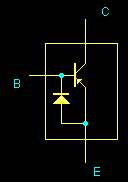
With this arrange, using the transistor with gain 157, I ended
with a "compound gain" of 52. I found that moding just
the input transistor was enough to get a good sound, but you can
experiment with the output too. The following measurements were
made with the mod applied.
Q1 (input) |
Q2 (output) |
|
| Collector | -0.590 V |
-4.5 V |
| Base | -0.049 V |
-0.590 V |
| Emitter | 0 V |
-0.540 V |
NOW, Q2 is biased! The wave form at the collector of Q1 is very similar to what we had before, only "smashing" of the top needs more input to happen. But at the collector of Q2 things are radically different.
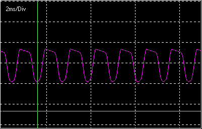
The bottom is "smashed", and the top is clipped. If we
increase the input, the bottom gets clipped too. These
characteristics make the thing very musical sounding and touch
sensitive. If the input is lowered, things clear up:
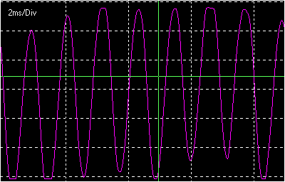
Soundwise: If we play soft, or lower the volume on the guitar,
the sound breaks a little or even gets clean. As we play harder,
distortion increases and can get very heavy. As the notes die,
they slowly clean up and gently vanish into silence. The sound is
very dark and smooth sounding, and is best suited for single note
work when you are at full fuzz. Sound sample here
Some people might miss the "noise gate", as it's a
funny sound. They just need to put a switch to put the diode in
and out of the circuit. In my FF copy I called this switch the
"ugly/beauty" switch. Hear the "ugly" position
WARNING: This mod will only work if both the transistor and
the diode are Ge devices.
Now, for the second mod. This is easier to explain and also very
easy to implement. If you change the input cap to 0.022 uF, you
will cut lows. As the thing already cuts highs by its own, you
end with a midrange emphasized sound, less smooth and dark and
more aggressive and nasal, like a "browned" British
amp... Sound sample here. I put a switch to choose between stock (2.2 uF)
and moded capacitor, and called it "classic/brit"
switch. By the way, I changed the output capacitor to 0.1 uF, I
like it bassier, but it's a matter of taste.
You can couple these mods with a pot in series with the input
(very useful if you are using a wha pedal) and/or a pot at the
collector of Q2 (does not makes a huge difference), to have one
the most versatile FF on earth...
I've come across
another mod that won't alter the sound but is intended to
increase the stability of the biasing of the transistors. The FF
is famous for working fine sometimes, bad a lot of times, and
simply don't working when you most need it (in SRV words,
"sometimes it just dies"). The main reason is the
variation of the transistors parameters with temperature.
There are three main parameters that will affect the bias when
the temperature changes: the gain (HFE),
the magnitude of the base-emitter voltage drop (VBE)
and the saturation (leakage) collector current (IC0).
Gain will increase with temperature, VBE
will drop at a rate of -2.5mV/oC and IC0
doubles for each 10oC increase in temperature. Ge
devices have much greater values of IC0
than Si (about a thousand times), so for Ge devices the most
important variation is that of IC0,
while for Si VBE is what cares most.
This is one of the reasons that Si transistors became more
popular than the Ge ones: it is much more stable and as a
consequence it can also stand more power before thermal runaway.
There's one trick designers used to do at the golden era of Ge
transistors to compensate for the variation of IC0.
It consisted of placing a Ge diode (reverse biased) in parallel
with the base-emitter junction of the transistor:
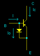
Since the diode is reverse biased, the current through it will be
its leakage current I0. Current through
the base will then be IB=I-I0.
Collector current will be IC=HFE*I-HFE*I0+(HFE+1)*IC0.
If HFE is much greater than one and I0
varies with the temperature the same way as IC0
does, then one variation will cancel the other, leaving IC
constant.
This stabilization is most necessary at the input transistor of
the FF. At the output transistor, there's the 1k pot at the
emitter that will help to stabilize variations in all three
parameters. You should not note any difference in sound, unless
you have a very leaky transistor or diode. It will only make any
difference the next time you have to play that gig at some
beach's Summer festival... If you only play in studios or in your
bedroom, it's better not to make this mod, to avoid the risk of
damaging your precious Ge transistor while you are soldering the
diode!
All sound samples in this page recorded with a Strat style guitar, humbucker at the bridge. FF gain always on max. Amp is a Washburn VGA-15 (a nice little amp) miked with a SM-57.
This page hosted by ![]() Get your own Free
Homepage
Get your own Free
Homepage