>

gallo magnetix
Notes to / from Self
Observations
10 March 2006
Since Moving in 2004, the MGB has languished in a plastic tub in a shelf in the garage. Recent thoughts of restarting the project include:
Available New Technology:
- TVT Small Portable NTSC bit-mapped monochrome video
- IDE Compact Flash Read/Write Capability
Some Consideration:
- Reconfiguration of the Packaging Concept
- Integration of other projects previously
envisioned as stand alone.
Modulation Software Overview
Modulation Routing
20 August 2004
Modulation Software Overview
 The MGB Host Processor provides 16 bits of control voltages for:
- The 2 MGB analog VCO's,
- A companion MG-1 Synthesizer,
- An AUX (or casual) VCO output (with Gate/Trigger),
This control voltage is the composite of a ;
- 7 bit MIDI "Note Value"
- 14 bit MIDI "Pitch Bend"
- 16 bit programmatic "LFO"
- 16 bit programmatic "ENVELOPE"
- 16 bit programmatic "NOISE"
When "switched in", MIDI Note values and Pitch Bend composite into the VCO control voltage without adjustment (or subject to any external MIDI programmed adjustment). The LFO, Envelope, and Noise each have a USER or PRESET derived "% of modulation" characteristic, a Level value. The Frequency and Level of the LFO; The Envelope ADSR, Delay and Level and; The Noise "algorithm" are also USER Adjusted.
The individual VCO control voltages, exhibit additional independance besides just the ability to adjust the "level" of any or all of the common modulators, but also correlates (or is activated) by a potentially different MIDI Note. The assignment ave some independance. As an example, while MGB's VCO 0 is the composite of Envelope 0, LFO, and Noise, VCO 1 is a componsite of Envelope 1, LFO 0/90/180 degree LFO wave offset, and Noise true or complimented.
The companion MG-1 composites similar to VCO 0, as AUX composites similarly to VCO 1, however, MGB VCO 0 and VCO 1 are typically also composited with the HIGHEST sounding MIDI Note while the MG-1 composites with the lowest sounding MIDI Note (unless tracking the MGB). The AUX composites with a user preference of Highest/Lowest/Second-Highest Note assignment
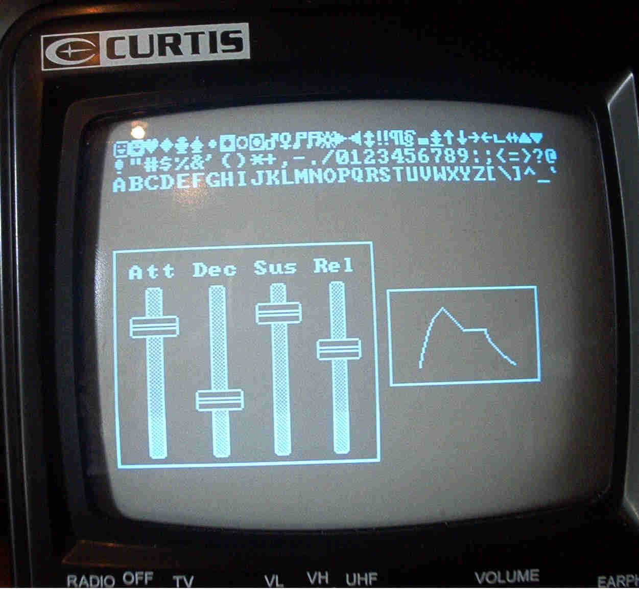
Programmatic Envelopes
21 May 2004
20 June 2004 - Mezzanine Construction:
A page documenting Mezzanine progress started.
16 June 2004 - MGB Mezzanine:
Experiments with the Serial DAC (AD8804) and algorithms for the generating 8 ADSR's, LFO and Random Noise modulators argued for an independant, dedicated, high speed microcontroller implementing as a "modulation peripheral". Looking to the MGB Host Processor as a byte wide "mail box", this is a write only peripheral to which you specify device (ADSR/LFO/NOISE/LCD), parameters, and "GATE".
"Daughtering" as it does to both the MGB Host Processor Board and the Analog Motherboard, i refer to it as the MGB Mezzanine Processor. Modulation Processor might be more suited.
The Processor consists of a DS89C420 microcontroller executing @32MHz and a 9 Bit FIFO input channel to which the MGB Host writes Device, Param, and GATE data.
Of the 8 ADSR modulation sources, 6 are 8 Bit Control Voltage sources, 2 are 16 Bit Control Voltage Sources. These Control Voltages augment the MGB Host's four 16 Bit Control Voltage Sources to drive the MGB and MG-1 analog circuitry.
Mezzanine Schematic
Being an '8051 derivitive, the DS'420 easily executes the exact code that currently executes in the MGB Host Processor (MSC1211). The DS'420 also is In Circuit Programmable with a little support circuitry. In order to not duplicate this circuitry for every DS'420 project, a remotely connecting PCB is used and the MPP need only supply a connection point and some pull-up resistors.
Off Board Programmer Schematic
Envelope Execution Rate:
In context with the discussion below regarding sample rates, the DS'420 executes many common instructions (accumulator referenced instructions) in a single clock cycle. The Envelope Routines are largely comprised of these instruction types. Multiple clock instruction come in to play a the time of table look up as most data is 16 bit.
Using a 16MHz crystal and employing the DS'420 clock multiplier a single clock instruction executes in 31.25 nS. Now to ballpark maximum envelope execution rate, we'll ignore the clock multiplier by saying we'll give 1/2 the cycles to the Foreground and 1/2 the cycles to the background (envelopes). Employing this fiction we can estimate the maximum envelope execution rate. Twelve DAC Channels can be updated in 100us. tThis corresponds to a 10kHz rate.
The DACs are fitted 1KHz 18-dB/8ve reconstruction filters which means at 8kHz these filters attenuate to -72dB. So any sample rate at or above 8kHz looks like a good sample interval. Also, the foreground is executing at the rate of a 16Mhz DS'420 which is to say, fast.
6 June 2004 - MGB Modulators:
Working Envelope Generators, LFO, and Noise. Look like 1ms. is a good choice for minimum Attack,Decay or Release time for the programable Envelopes. Envelopes are samples from a Sine Table. The rate at which these samples a presented to the DAC sets the minimum ADR times. So currently the plan is each envelope generator has a
- 3kHz sample rate;
- 1kHz 24db/8ve filter;
- 256 word sine table.
Modulation Interval: At 3kHz, the sample interval occurs every 333us. The MIDI interrupt occurs with higher priority so it isn't blocked by the Modulation Timer which fires off the envelopes, lfo, and noise. The front panel LCD, rotary and motorized slider pots, however do require service time but are by nature slower than the Envelopes.
Foreground/Background Interval: Front panel controls input to the MSC1211 24 bit ADC so it's sophisticated hardware off loads processing and provides a slow maybe 100 Hz sample rate (mostly for the motorized pot setting recall). The Motorized pots can move end to end in 1 second so the interval of 100Hz would allow quick recall of pot postition. The LCD has 1024 bytes to update for a full display write. Writes to the LCD that are too slow are a frustrating impediment so perhaps 1/2 of the 333us interval is required for a foreground "Front Panel" interface.
Modulator Core Execution Rate: So 10 modulation sources are required to execute in ~166us. The MSC1211 executes @24 MHz and it's shortest instruction is 4 cycles. This 6MHz minimum execution rate allows for 996 instructions to occur per 1/2 cycle of 166us. This allows 100 instructions per modulator.
Routing: A portion of the 100us allocated to each modulator must be allocated for it's Scaling (Modulation "Level"), and the potential combining of any and all modulation sources for output through a DAC channel.
DAC Update Timing: 22us is needed for the serial DAC update so 264us are required for this task(12 DACs=10 modulators).
Modulator Core Routine An envelope generators routine has a core comprised of a 24 bit Phase + Increment addition, Sine Table Lookup, Evaluation, and Value Storage for Routing. This core executes in approximately 16 instructions (2.6us).
Core Application: The core is wrapped inside a specific ADSR Mode. As an example, the Attack mode occurs for a Note Activation.
Attack mode: The Attack mode interrupts any other mode be it Decay, Sustain or Release. This "Re-Trigger" characteristic occurs for each new assigned Note Activation. The Attack value is derived by "riding" the up-slope from minimum to maximum (0-128) of the Sine Wave stored in the Sine Table. These samples are progressively read from the table with an index equal to the Current Phase (24 bit) plus Rate of Table Increment (also 24). Sine Table Values are stored for scaling and routing. Should the Sine Table Pointer equals or exceeds 128 (last positive Up-Slope table location), instead of reading a table value we "saturate" at Max Level, clear the Attack mode and start the Decay mode. Attack cycles that interrupt another mode, progresses upward, at the Attack Rate of Increment, from the current Decay, Sustain or Release value.
Decay and Release mode: Each of these modes "ride" the same Sine Table Slope but in the reverse or "down" direction. This is the negative going Maximum to Minimum value Direction. Each mode has it's own Rate of Increment and each "saturates" at minimum value when the Sine Table Pointers is equal or "less" than 0 (minimum Sine Value).
The Decay mode occurs only when we reach maximum Attack value. This means it always "starts" at the highest value location and decends down the table to minimum value. The Release mode occurs because a Note is Now OFF. This can occur at any time in Attack, Decay or Sustain modes. No matter what mode it terminates, it rides down from the current Table Value to minimum value at it's Rate of Increment. Fast note activations with slow Attack rates can mean the Decay mode never occurs because the Attack cycle was not over when the key was release.
Routing:Modulator Values are not output directly. The 12 DACS that connect to the MGB analog circuitry output a user specified value which is the sum of any or all modulations (plus static values). Each Modulator value can be adjusted or "scaled" prior to mixing with other Modulators. This is the Percent of Modulation or Modulation Level control which means each DAC (MGB control portal) has a 10 input mixer function in front of it.
Using 8 and 16 bit Converters :
The MGB has four 16 bit and twelve 8 bit Digital to Analog Converters. The 16 bit converters provides "drive" VCO Frequency Control Voltage. The Frequency and modulation for a given VCO is combined and output by a 16 DAC. . The twelve 8 bit converters are used in two different ways. VCA's, PWM, output to an single 8 bit converter. VCF's are driven by two 8 bit DACs which are summed in a weighted fashion to prove ~12 bits of control accuracy.
Interestingly this provides for 3 voice Polyphony. This is due to the MGB VCO's being driven by independant 16 bit DACS. The MG-1 is driven by a single 16 bit DAC, and an auxiliary synth is provided for by the remaining 16 bit DAC.
A Three Voice synthesizer is probably somewhat eccentric. A four voice synthesizer would be more typical and i could provide for four synthesizer "voices".
- The MGB VCO pair;
- The MG1 VCO pair;
- A single VCO/VCF/VCA CEM Board;
- A ENS-76 style Modular 2 Voice Synthesizer.
Maintaining the independance of the MGB oscillators is done to fully exploit Linear and Exponential Modulation between the oscillators. Also as each VCO is provide a VCA, VCO independance allows for great timbral variety.
Applying 8 bit converters :
While 8 bit conversion is sometimes "sneered at", it's actually quite appropriate for audio and control amplitude adjustment. Take the case of a VCA. Using an Irwin Electric hi-quality SSM2164 VCA perhaps 100dB of dynamic range could be expected with a Signal to Noise not far removed from this value. Applying an 8 bit converter this provides ~2.5 bits per dB for linear voltage control. This amounts to .4 dB of control, a more than respectable amount. VCA's can be found in other places than just the "Volume" department of a synthesizer. Resonance and Envelope Control Sources can also use VCA circuits.
Now this fine resolution noted above is not achievable if the 8 bit DAC directly generates amplitude (where 58 dB is best case) instead it is achieved when driving (or controlling) a linear circuit like a VCA.
MGB incorporates 4 VCA's. Two VCA's take the place of the Volume Controls that synthesizers use to "mix" the level of VCO's prior to downstream alteration using VCF's or other circuits like another "overall" VCA.
The remaining two VCA's are deployed such that one provides "Resonance" for the MGB Ladder Filter, and the remaining circuit, as the overall Synthesizer Output VCA.
Other MGB Topics:
Current MG-B Design Information:
VCO Detail
VCF Detail
VCA Detail
MIDI Control