 MIDI Control Surface
High Level Definition
This MIDI Control Surface presents the instrumentalist with rotary potentiometers, joysticks, push button switches, and a Liquid Crystal Display. The Users intention (as expressed by use of the controls and switches) issues to external MIDI devices and displays upon the LCD.
Conceptual Design
There is nothing conceptionally new about this Control Surface, it's a child of it's time. An popular community of alternative designs for similar functionality can be referenced here: "Free MIDI DIY Projects by Thorsten Klose".
Practical Criteria
The following design is a sophisticated instrument designed to conserve the amount of components and assembly effort. The foregoing influenced the selection of every capabilility and component. This is demonstrated in the degree of integration engendered by the Microcontroller, Multiplexer/ADC combination, clocked serial Port Expanders, and the potentiometers motor drivers.
The panel controls, indicators and methods, that are employed within this control surface device, list below.
- 16 motorized Parameter Controls
 Each Control is Soft Assignable to any specific MIDI Channel, Status or Control type.
- 2 manual Joysticks
2 axis, each soft assignable, as well as, response programmable (how fine, exp vs lin, etc)- 40x2 Character Mode LCD
Use of Custom Characters allow Vertical or Horizonal bar graph display, Clear phaseology indicating which synth, what state and, next step.- 4 MACRO Buttons
Button activated issuance of MIDI Events- 4 Function Buttons
Select and activate Device features.- Rotary Cursor Controls
Manual LCD display format navigation. - 2 manual Joysticks
Rotary MIDI Parameter Controls: Any of 16 Rotary Controls programably assign to MIDI channels, message types and, either of two MIDI output ports. A rotary control supplies the "value" (from 0 to 127) inserted into an assigned MIDI Message. A Rotary control setting can be saved and recalled as an individual or group "Setting". The potentiometer's motor returns the last saved setting for each control and instrument combination.
 Manual Non-Rotary Controls:
Two Joystick Controls (comprised of two potentiometer controls each) assign as "Coarse" and "Fine" for a single parameter or provide simultaneous, two-axis control, for two different selected parameters. The joysticks are manual, not motorized.
Manual Non-Rotary Controls:
Two Joystick Controls (comprised of two potentiometer controls each) assign as "Coarse" and "Fine" for a single parameter or provide simultaneous, two-axis control, for two different selected parameters. The joysticks are manual, not motorized.
Rotary Cursor Control: Two non-motorized rotary Cursor Controls allow rapid movement between display select or entry locations. One control provides Left/Right motion while the remaining control provides for Up/Down motion.
Button Activated MACRO Messages: The "Macro" Buttons send a User programmed sets of MIDI Messages when pressed. The "Macro" can be a single message sent upon keypress, or a "scripted" group of MIDI messages.
Function Buttons: The remaining Control Buttons Mode, Function, Cancel and, Select communicate the instrumentalist's intentions to the Control Surface. Using these buttons in concert with the cursor control "knobs", Settings, Profiles, Macros are reviewed, edited, stored, cataloged and recalled.
Visual Format Display: The 40 character by 2 line Liquid Crystal Display provides for visual indication. As a non-graphic display, coarse vertical Bar Graph or fine horizonal Bar Graph magnitude representations are achieved psuedo-graphically using 8 programmable character "tiles". Instrumentalists use the LCD as a 2 line "view-port" into larger display formats. The rotary cursor "etch-a-sketch" control format compliments this representational technique.
Control Surface Integration: Control Surfaces are common in DAW applications providing a "mixing desk" operator interface for software executing on a computer platform. As such, the Computer "hosts" the control surface. This control surface intends to drive the MIDI "chain"
Control Selection Strategy: Intended to host multiple instruments, each instrument's "setting" is editable, storable and recallable. The entire control surface control compliment can be dedicated to an individual synthesizer or individual controls can be assigned to various synthesizers. . A "setting" is just the image of the current assignments and values. Motorized potentiometers allow a recalled setting to be automatically restored as a "stock" voicing or continuing development.
Instrument Profiles: Profiles are ready to go (previously created) starting points intended to accomodate the approach to a specific instrument. The concept is to logically allocate controls (i.e. ADSR being contiguous ) that are well supported by the LCD Display (decimal numbers, english phrases).
Control Technology: Rotary motorized potentiometers are much slower than their linear counterpart. They do allow a more fine and repeatable setting. While motorized linear faders "snap" nearly immediately into position, motorized rotary potentiometers can take many seconds (8 typical) to achieve full rotation.
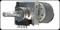 The rate of end to end travel of the rotary potentiometers is the result of the "transmission" which is geared very fine. In fact, this granularity is finer than most human operators could manually repeat. This holds open the possibility that the Control Surface could enhance the operators ability to achieve very fine parameteric specification.
Recalling that MIDI provides for for 7 bits of Coarse and 7 bits of Fine specification (across two distinct messages), the right MIDI device can exploit this capability. Machine assisted parameter specification would perform to let the Operator to "bump" the motorized pot to a precise parameter setting.
Additionally, many MIDI parameters are nominal at mid-scale. This results in many settings not requiring "end to end" travel to achieve a recalled setting value.
| Midi Control Surface Hardware Section | Schematic |
|---|---|
| The Central Processor (a high-speed 8051 variant), two MIDI ports, 40 bits of Motor direction/enables, "mux" addressing, and a 40x2 LCD); | Central Processor |
| 24 Input Analog Multiplexer and 8 bit Analog to Digital Conversion | Analog to Digital Conversion |
| The Motor Controller (16 motors driven with Left, Right and Enable/Disable signals)and Power Supplies. | Motor Drive - Interface |
The following page provides additional Architectural Description .